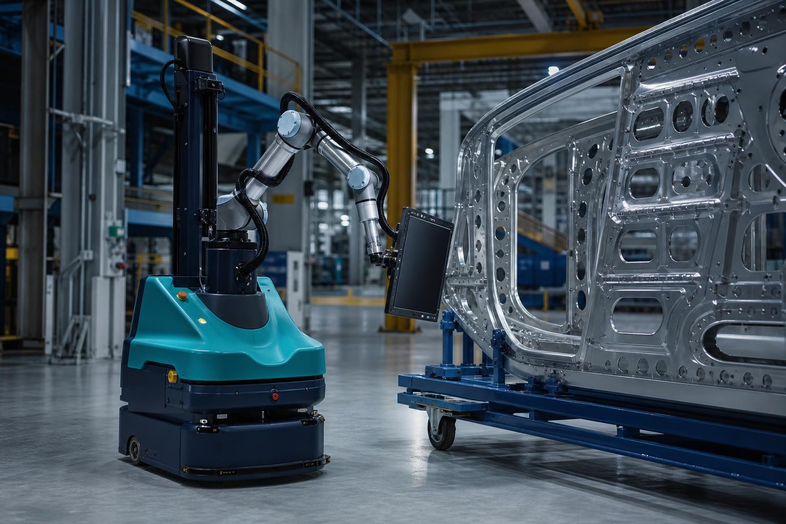
In many machine shops an operator's day is measured in footsteps. They load a blank on the first machining centre, close the door, start the cycle and walk to the next machine, where another part has just finished; by the time they get back to the first, the spindle has been idle for a few minutes. The machines wait for the operator, and the operator spends much of the shift walking with parts weighing a few kilos. This is the ground on which mobile manipulators have been offered for some years: an autonomous mobile robot (AMR) carrying a robot arm, often a collaborative one, and a camera that finds the working position precisely at every stop.
The review by Hvilshøj, Bøgh, Skov Nielsen and Madsen in Industrial Robot (2012) was already measuring the gap between research prototypes and factory requirements, and the review by Ghodsian and colleagues in Sensors (2023) finds that the industrial applications it surveyed cluster in logistics (49%) and manufacturing (33%). Since then, catalogue products have arrived, the standards have changed and Italy remains the second-largest European market for industrial robots: according to the IFR World Robotics 2026 report, installations in the country reached about 7,800 units in 2025, 11% fewer than the year before. What remains is to understand when an arm that moves earns more than one that stays put.
One arm moving between several machines: where the advantage comes from
A fixed robot in front of every machine tool makes sense when the machine runs many parts on short cycles, because the arm stays busy for most of the shift. In SMEs with small batches and long cycles the opposite happens: the robot loads, unloads and then waits through the twenty or forty minutes of machining. The group of Vaher, Otto and Riives at Tallinn University of Technology starts from exactly this point in two papers from 2020 and 2021: many small companies lack the workload to keep a robot busy at a single station, and the deciding indicator is equipment utilisation when one collaborative arm, carried by an AMR, serves several cells in turn.
The calculation rests on the ratio between the time the arm spends at a station and the machine's cycle time. With a thirty-minute machining cycle, a four-minute robot intervention covering door opening, unloading, loading, blow-off and restart, and another two minutes to travel and realign, a single manipulator can in theory tend four or five machines. These are round numbers, because in practice the cycles are not synchronised and some machines finish while the robot is elsewhere. The principle holds, though: the longer the machine cycle relative to the intervention, the more machines can share the same arm.
Fixed robot with a shuttle or mobile manipulator: the machine cycle decides
The mobile manipulator has a direct and often sturdier competitor: a fixed robot in the cell, with an AMR or a shuttle delivering parts on trays, drawers or pallets. In that configuration the arm works on a rigid, already referenced base, accuracy is that of a conventional installation, and the mobile robot only transports, the job in which AMRs are most mature. The differences between vehicle types are covered in the comparison between AGVs and AMRs.
The choice can be read from the cycles. With short cycles, high cadence and a single machine to serve, the fixed robot almost always wins, because it wastes no time travelling and does not have to find its position again at every intervention. With long cycles, many different machines and batches that change every week, the mobile arm spreads the same investment over several stations. In between lies a case common in machine shops, where floor space tips the balance: there is not always room for a fenced cell in front of a machine tool, whereas a manipulator that arrives, works and leaves keeps the machine accessible for set-ups and maintenance.
Thirty, thirty-five kilos: the physical limit on payload
On the datasheets of catalogue mobile manipulators, arm payload currently tops out at around 30-35 kg. Above that threshold the offer changes in nature. You find engineered-to-order solutions, platforms that dock the robot at fixed stations before it works, or a fixed robot served by a transport vehicle. The main reason is stability.
In a simplified example, a 400 kg base with its wheels 30 cm from the centreline resists sideways tipping with a moment of about 120 kg·m. A 30 kg part held 1.2 m from the centreline, so 0.9 m beyond the tipping edge, generates 27, plus the overhanging share of the arm, and the margin still copes with braking. With 100 kg at the same distance the part alone generates 90 kg·m and the static margin drops below 1.5, before counting an arm that at that payload weighs hundreds of kilos and shifts the centre of gravity forward as it extends. Recovering the margin means widening and ballasting the base, up to masses and footprints that no longer fit between the machines of a production department.
The rated payload also includes the gripper: with a 5-8 kg gripping tool, a 30 kg arm handles parts of just over 20 kg. The stability check with the arm extended and the vehicle braking should be requested in writing, with the calculation.
From centimetres to hundredths: how vision recovers the base error
A mobile base never stops twice at the same spot. After navigation, the offset from the theoretical position is measured in millimetres, sometimes up to a centimetre, depending on the navigation system, the floor and any docking references. A robot arm, measured on a fixed base with the methods of ISO 9283, repeats its pose within a few hundredths of a millimetre. A part that goes into a vice with clearances of a few tenths therefore requires the base error to be measured and corrected at every stop. Heimann and colleagues say so at the start of their mobile machine-tending paper presented at ETFA 2023: available mobile robots, on their own, do not provide the accuracy needed to insert workpieces into a fixture.
The most common correction uses a camera on the robot wrist and a fixed reference on the station, such as a printed marker, a plate with calibrated holes or the profile of the vice. The robot stops, frames the reference, computes the offset between expected and actual position and shifts the whole pick-and-place program accordingly. This is the approach described by Vaher, Otto and Riives in 2020, in which vision compensates for the platform's imprecision and the arm positions itself relative to the object rather than to the map. Alternatively, mechanical centring cones or probing a reference are used, slower but independent of shop-floor lighting.
Two precautions weigh on the result. The first concerns the fixture: lead-in chamfers, self-centring vices and tapered pins absorb the residual error that vision leaves, and cost far less than a more accurate camera. The second concerns how you measure. A vehicle's docking repeatability is verified with statistical methods, such as those in ASTM F3499-21 on autonomous vehicle docking, and it pays to ask the supplier to demonstrate it on your floor, at the real station, before acceptance.
Who signs off safety when the arm rides on a mobile robot
Conformity of a mobile manipulator is signed by whoever puts the complete assembly into service, usually the integrator or the manufacturer of the complete system, and their job is complicated by a gap the standards openly declare. ISO 10218-1:2025, published in February 2025, treats the industrial robot as partly completed machinery and excludes from its scope the hazards of mobility when the robot is mounted on a driverless industrial truck or a mobile platform. The moving part falls under ISO 3691-4:2023 on driverless industrial trucks, and the integration of the robot into the application under ISO 10218-2:2025. Neither covers the whole assembly, and the risk assessment under ISO 12100 has to bring the two worlds together: the arm moving while the base travels, the laser-scanner protective fields active at each station, the robot working next to an operator.
The 2025 revision also changed the vocabulary of collaborative applications. The comparative analysis by Hartmann and colleagues, published on arXiv in 2026, documents that the technical specification ISO/TS 15066:2016 has been absorbed into ISO 10218-2:2025. Power and force limiting becomes a normative requirement, the table of pain thresholds for 29 body regions survives as informative Annex M, and the separation-distance formulas for speed and separation monitoring move into normative Annex L. The term collaborative robot disappears, replaced by collaborative application. Safety therefore depends on how the arm is used, and for a robot that changes station five times an hour it has to be verified station by station.
In the United States the issue is addressed more directly. The ANSI/A3 R15.08 series classifies an industrial mobile robot with a manipulator as Type C; Part 2 (2023) covers the integration of systems and applications, and Part 3, published in April 2026, the duties of users, including a risk assessment to be repeated when the application or the environment changes.
In Europe the date to mark is 20 January 2027, when Regulation (EU) 2023/1230 replaces the Machinery Directive. Two changes matter for mobile manipulators. The essential requirements in Annex III include protection of control systems against corruption, so cybersecurity becomes part of the declaration of conformity. Machinery that entrusts safety functions to systems with self-evolving behaviour based on machine learning, on the other hand, falls under Annex I, Part A, with mandatory involvement of a notified body. Vision that merely corrects the arm's pose does not perform a safety function; a system that protects people with trained models could fall into that category, and the specification must make this clear. The return of safety on the project is covered in the article on AMR safety.
Batteries, doors and signals: integrating with machine tools
The stated run times of mobile manipulators range from a few hours to around a dozen, but the datasheet figure says little unless you know the duty profile it was measured on. An arm working almost continuously draws from the same battery that drives the base, and the real shift gets shorter. The most common strategy is opportunity charging, with short stops at the charger while the machines are cutting, which still take time away from interventions and belong in the calculation, as explained in the article on charging station sizing.
The machine tool, for its part, has to become the robot's counterpart. At a minimum you need an automatic door or a controllable opening, status signals (cycle complete, door open, vice clamped, alarm) and a cycle-start command, exchanged through digital I/O or a fieldbus, with safety-relevant signals handled by a dedicated safety interface. On recent machines the status can also be read over OPC UA. The OPC 40501-1 specification, developed by VDW and the OPC Foundation, describes machine-tool state, jobs and alarms in a uniform way, which helps when the same robot serves machines from different builders. On an older machine without an automatic door the retrofit weighs on the budget more than people expect. And if other mobile robots already circulate on the shop floor, a fleet that speaks an open protocol such as VDA 5050 does not tie future growth to a single supplier.
The feasibility study starts from the parts, not from the robot
Anyone evaluating a mobile manipulator tends to start from the robot's datasheet. It is better to reverse the order and begin with the list of part numbers, because almost all the answers are there. The data to collect are few and mostly already in the company:
- Parts: part numbers, weights, dimensions, material, gripping surfaces and any fragility, plus the gripper weight.
- Loading tolerances: vice or fixture clearances, required orientation, presence of lead-in chamfers.
- Cycles: cycle time of each machine per part number, batch size, changeover frequency.
- Flows: where blanks come from and where finished parts go, distances, doors, slopes, aisle widths.
- Machines: door type, CNC control, available signals, free space in front of the loading area.
- Shifts: staffed and unstaffed hours, people present along the routes.
With these numbers the study answers four questions: how many interventions per hour the manipulator can perform, charging included; how many machines it can serve without leaving them idle for too long; which parts fall outside the envelope because of weight or tolerance; and which configuration is preferable, a mobile arm or a fixed robot with a shuttle. The method for turning the result into an economic return is the one in the analysis of ROI, TCO and payback, and the flow analysis follows the same logic described for autonomous forklift projects.
The prudent step after the study is a pilot on two or three machines with an exit condition written before starting and valid both ways. If the manipulator reaches the expected interventions per hour and the agreed percentage of successful picks, it is extended to other machines; if it falls short, you go back to a fixed robot or redesign the flow before buying anything else. The threshold is set by the buyer, because no standard states how many picks out of a hundred must succeed, and it belongs in the specification together with how they are counted: on which part numbers, over which time window, with which definition of a failed pick.
When a mobile manipulator is the wrong choice
Some conditions argue against the mobile arm, and it pays to recognise them early. Parts that exceed 25-30 kg with the gripper, cycles of a few minutes on a single machine, loading tolerances in the hundredths without chamfers or centring, uneven floors or slopes between stations: in each of these cases a fixed robot, a dedicated loader or an automatic pallet changer does better and with less risk. The same applies when the real problem is transport between departments, which an AMR without an arm solves with a smaller investment.
Where cycles are long, parts stay within a few tens of kilos and machines outnumber the available operators, the mobile arm becomes attractive, above all for covering lightly staffed shifts. The next step is to put the list of part numbers and the cycle times into a feasibility study that states how many machines to serve and with which configuration. The available technologies are described on the page on industrial automation and material-handling robotics; to start from your own data, PITECH sets up the evaluation before proposing any machine.
Frequently asked questions about mobile manipulators
What is a mobile manipulator?
It is an autonomous mobile robot (AMR) or automated guided vehicle carrying a robot arm, often a collaborative one, and usually a camera. The base moves between benches, machine tools and cells; the arm loads and unloads parts after using vision to correct the base's positioning error. In the US ANSI/A3 R15.08 standards it corresponds to a Type C industrial mobile robot.
How much weight can a mobile manipulator handle?
In catalogue solutions arm payload currently reaches about 30-35 kg including the gripper, so the parts it can handle weigh somewhat less. Above that threshold the stability of the base becomes the limit, and the options are engineered-to-order solutions, platforms that dock the robot at fixed stations, or a fixed robot served by an AMR or a shuttle.
Is a mobile manipulator accurate enough to load a machine tool?
Yes, provided the base error is corrected at every stop. The base stops with offsets of a few millimetres, while the arm repeats its pose within a few hundredths. A camera reading a reference on the station, together with vices and fixtures with lead-in chamfers, brings the residual error within the clearances the loading requires. Repeatability should be demonstrated on your floor before acceptance.
Which standards apply to a mobile manipulator in Europe?
For the arm, ISO 10218-1:2025 and, for integration and collaborative applications, ISO 10218-2:2025, which has absorbed ISO/TS 15066. For the mobile base, ISO 3691-4:2023. Because ISO 10218-1 excludes mobility hazards, the ISO 12100 risk assessment must cover the whole assembly. From 20 January 2027 the EU Machinery Regulation 2023/1230 applies, including cybersecurity requirements.
When is a fixed robot with a shuttle better than a mobile manipulator?
When machine cycles are short, cadence is high and there is only one machine to serve, or when parts exceed 30 kg or loading tolerances are very tight. In these cases the fixed robot works on a rigid, already referenced base, and the AMR or shuttle only transports the parts.
How do I request a feasibility study from PITECH?
Send the list of part numbers with weights and dimensions, the machine cycle times, batch sizes, a floor plan of the department and the type of doors and controls on the machines. With these data PITECH estimates how many machines a manipulator can tend and which configuration is preferable, before any quotation. You can use the contact form, WhatsApp or info@pitech-solution.com.