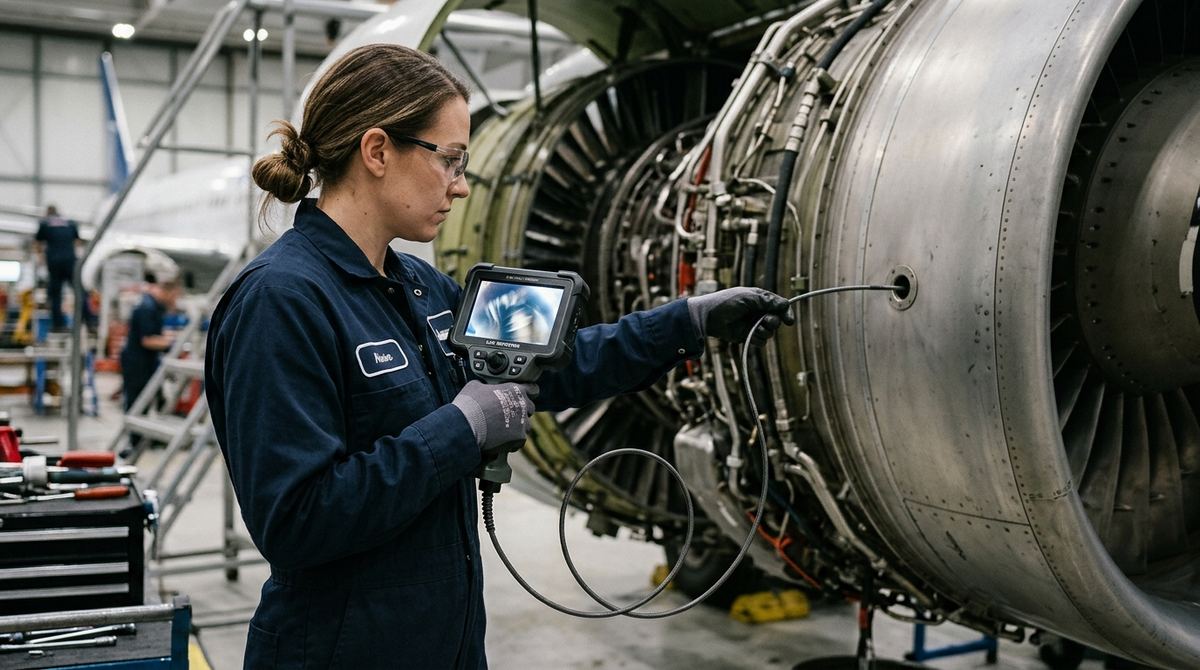
On a gas turbine or an aero engine, disassembly is the most expensive intervention there is: downtime, specialist labour, spare parts, recertification. Borescope inspection — the remote visual examination performed through the access ports designed in by the manufacturer — is what lets you know the condition of the gas path without disassembling, and therefore decide on data rather than assumptions. This guide is applied: it does not explain how to choose a videoscope in general (see the dedicated guide on choosing an industrial videoscope), but how to set up a borescope inspection on turbines and engines and what it takes to do it well.
What borescope inspection is and why it is the reference check
Boroscopy (or videoscopy) is the remote form of visual testing (VT), the oldest of the non-destructive testing methods. A modern videoscope is a flexible probe with an image sensor at the tip, LED illumination, controlled tip articulation and, on high-end models, 3D measurement of indications. Engine manufacturers design in a set of borescope ports: threaded, plugged holes distributed along the gas path, giving access to the compressor stages, the combustor and the turbine stages.
The reason borescope inspection is central to maintenance programmes is economic before it is technical: the hot sections of an engine accumulate progressive damage (thermal fatigue, oxidation, erosion) and the only alternative way to see them would be disassembly. In aircraft maintenance programmes managed under Regulation (EU) 1321/2014 (Part-M/Part-145), borescope inspections appear both as scheduled inspections at OEM-defined intervals and as unscheduled inspections after events: suspected foreign object ingestion (FOD), overtemperature/hot start, compressor stall, abnormal vibration.
Typical defects, zone by zone
Each engine section has its own damage mechanisms. Knowing them in advance is what separates an inspection from a "guided tour":
| Zone | Typical defects | What to look at |
|---|---|---|
| Compressor (fan and stages) | FOD damage (nicks, dents, tears, curls), airfoil erosion, leading-edge cracks, tip rub | Blade leading and trailing edges, blade roots, contact traces on cases and abradables |
| Combustor | Thermal cracks, burn-through, distortion, thermal barrier coating (TBC) spallation, injector coking | Liners and domes, areas around dilution holes, fuel nozzles, igniters |
| Turbine (NGVs and blades) | Thermo-mechanical fatigue cracks, oxidation and hot corrosion (sulfidation), coating loss, blocked cooling holes, creep signs, re-deposited molten material | Blade leading edges and platforms, trailing edges, seals, coating colour uniformity |
Two important points. First: FOD damage found in the compressor almost always requires extending the inspection downstream, because fragments travel through the engine. Second: classification matters as much as detection. A 0.5 mm nick on the leading edge of a compressor blade may be acceptable, blendable or a cause for rejection depending on the stage, the position on the blade and the limits tabulated in the engine manual (EM/AMM). The inspector does not decide "by eye": they measure and compare against the limits.
Planning the inspection: access, sequence, rotation
An effective borescope inspection is prepared before the probe goes in:
- Access map: the engine manual defines which borescope ports serve which stages, with the dedicated adapters and probe guide tubes. On many engines, certain stages can only be reached from specific ports at precise angles.
- Controlled rotor rotation: to inspect every blade of a stage, the rotor must be turned slowly and in a controlled way (manual or motorised turning tool), while the probe tip is held in a stable position as the blades pass in front of the optics.
- Sequence and counting: inspection proceeds stage by stage, counting blades from a reference (a marked blade or recognisable feature), so every indication is traceable to a specific blade and retrievable at the next inspection.
- Engine condition: engine cold, supplies made safe, igniters disabled, lockout procedures; in aviation the activity is managed as a task of the approved maintenance programme, signed off by authorised personnel.
- Documentation: photos and videos of every indication with position (stage, blade, zone), measurement, comparison against the limits and archiving in the engine records. Traceability across successive inspections is what allows a known crack to be monitored for propagation instead of the component being rejected at first observation.
The public reference guide for setting up visual inspection in aircraft maintenance is Advisory Circular FAA AC 43-204 — Visual Inspection for Aircraft, covering planning, human factors, lighting and borescope use. In industrial contexts (gas turbines for power generation, oil & gas), remote visual examination requirements — demonstrable minimum resolution, lighting conditions, procedure qualification — are codified in ASME BPVC Section V, Article 9, while VT personnel qualification follows ISO 9712.
Measuring indications: from stereo to 3D measurement
The operational decision (accept, repair, reject, shorten the re-inspection interval) depends on the size of the indication, not merely on its presence. Turbine-grade videoscopes offer stereoscopic or phase-projection measurement: the tip captures the image from two perspectives (or projects a pattern) and reconstructs the surface in 3D, allowing you to measure crack length, dent depth, missing-coating area, tip-to-blade distance. Three things must be verified in practice: the stated accuracy at the real working distance (tolerances degrade as you move away from the defect), the possibility of validating measurements on reference blocks, and repeatability between operators. A reliable 3D measurement turns borescope inspection from a qualitative check into engineering data on which the maintenance decision can rest.
The videoscope for turbines: specific criteria
Compared with general-purpose videoscopy, turbine work imposes precise requirements:
- 4 mm and 6 mm probe diameters: 6 mm is the reference for image quality, illumination and robustness; 4 mm is needed for narrow ports and passages. Interchangeable probes on the same base unit are a concrete operational advantage.
- Precise, stable 360° articulation: fine tip control, position holding (brake/hold) while the rotor turns, reliable return-to-neutral for safe extraction.
- Image quality and illumination: high-resolution sensor, highlight management on reflective metal surfaces, powerful illumination for combustion chambers, interchangeable optical tips (forward/side view, adequate depth of field).
- 3D measurement: stereo or phase projection, with documented, verifiable accuracy.
- Robustness: abrasion-resistant sheath, resistance to fuel and oils, tolerance of residual engine temperature, field case and accessories.
- Reporting: annotations, stage/blade tagging, export of reports comparable across successive inspections.
For these applications PITECH proposes JOINWE industrial videoscopes, with probes in the typical turbine diameters and 360° articulation; the general overview of the technology is on the industrial videoscopy RVI page.
In-house instrument or external service?
Many organisations start by entrusting borescope inspections to external services or OEM support. Bringing the instrument in-house becomes rational when: inspections are recurring (industrial turbine fleets, MRO, power generation with planned outages); immediate response capability is needed after events, without waiting for an external technician; or the avoided downtime pays for the instrument within a few occasions. External service remains preferable for episodic needs or when interpretation requires engine-type expertise not available internally — and in aviation, the maintenance organisation's authorisation remains in any case the constraint governing who can sign off the inspection.
To frame the evaluation, the correct path starts from the application: which engines or turbines, which access ports and diameters, which defects and acceptance limits, how many inspections per year. On that basis the configuration is defined (probe diameters, optical tips, measurement, accessories) and tested on the real case. PITECH supports this evaluation neutrally: describe your application via the contact page.
Frequently asked questions about borescope inspection of turbines and engines
What is a borescope inspection of a turbine?
It is a remote visual inspection (RVI) performed by inserting a borescope or videoscope through the access ports provided by the manufacturer, to examine the compressor, combustor and turbine without disassembling the engine. It detects and measures cracks, foreign object damage (FOD), erosion, corrosion, burns and coating loss on blades and gas-path components, comparing them against the acceptance limits of the engine manual.
Which defects can be found by borescope in an aero engine or gas turbine?
In the compressor: FOD damage (nicks, dents, tears), airfoil erosion, leading-edge cracks and tip rub. In the combustor: thermal cracks, burn-through, distortion and TBC spallation. In the turbine: thermo-mechanical fatigue cracks, oxidation and hot corrosion, coating loss, blocked cooling holes, creep damage. Every indication must be classified and measured against the OEM manual limits.
Which probe diameter is needed for turbine borescope inspection?
The most common diameters are 4 mm and 6 mm. The 6 mm probe generally offers a brighter image, better optics and higher robustness; the 4 mm probe is needed where borescope ports or inter-stage passages are narrow. The choice depends on the access ports of the specific engine: common practice is to have interchangeable probes in both diameters, with 360° articulation.
Does borescope inspection replace engine disassembly?
No: borescope inspection is the tool that lets you decide whether disassembly is needed. Maintenance programmes use it for scheduled inspections, checks after events (FOD ingestion, overtemperature) and monitoring of known indications. If indications stay within manual limits, the engine remains in service, possibly with reduced re-inspection intervals; if they exceed them, disassembly and repair follow.
Is a qualification required to perform borescope inspections?
In aircraft maintenance it is a specialist task carried out by personnel authorised by the maintenance organisation under Regulation (EU) 1321/2014 (Part-145/Part-M) and trained on the engine type; the FAA provides guidance in AC 43-204. In industrial contexts, VT personnel qualification is defined by ISO 9712 and remote visual examination requirements by codes such as ASME BPVC Section V, Article 9.