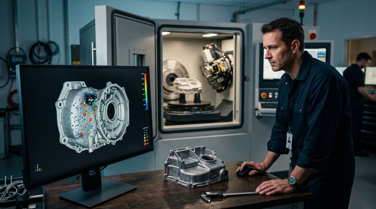
The pore that scraps a die casting is rarely the one final inspection finds. It's the one the milling cutter finds, when machining a sealing face opens a cavity that sat half a millimetre below the surface. By then the part has absorbed its full cost: metal, casting cycle, machining time. Porosity works that way. A void becomes critical only in relation to what surrounds it: the stock that will be machined away, the pressurized channel that has to hold, the section that carries fatigue load. Judging it takes more than knowing it exists; it takes knowing where it sits and how large it really is. That is precisely the information a radiographic projection doesn't contain, and the information industrial computed tomography delivers.
One Pore Is Not Like Another
Three different fates await a porous casting, and none of them depends on total void volume alone. The first is machining: a pore that is harmless in the raw part becomes a crater on a sealing face once the cutter removes the stock, and the discovery often happens on the assembly line or at the customer. The second is leak-tightness. In castings for hydraulic and cooling circuits, what matters is interconnected porosity, the path a fluid can follow through the wall, far more than any single isolated cavity. The third fate is fatigue.
On fatigue, the published evidence is unambiguous. Studying cast Al-Si alloys, Gao and colleagues (Fatigue & Fracture of Engineering Materials & Structures, 2004) showed that crack initiation depends on pore size and on how close the pore sits to the surface. A study in Scientific Reports (2017) put a number on how much position matters: surface and near-surface defects dominate initiation even when they are up to ten times smaller than internal ones. On the shop floor that reads as follows: a 300 µm pore in the core of a thick section may mean nothing, while a 100 µm pore just under a machined surface can set the life of the component. Judging porosity therefore takes two coordinates, size and position. The most widely used inspection method carries only one of them.
Where the Projection Stops
A radiograph is a shadow: everything the beam crosses through the wall collapses onto a single image. For detection, that principle works remarkably well, and the reference standards have turned it into a mature contractual language. ASTM E505 provides reference radiographs for aluminum and magnesium die castings, organized in series of four increasing severity levels covering gas porosity, shrinkage porosity, cold shuts, inclusions and oxide films; acceptance criteria are specified "in terms of these radiographs". ASTM E2422 is its digital evolution for aluminum castings: thirteen reference images across eight severity grades, for two thickness classes (6.35 mm for walls up to 12.7 mm; 19.1 mm for walls from 12.7 to 51 mm), distributed as 16-bit TIFF or DICONDE files. How radiographic testing of castings is set up and read is covered in our guide to radiography of welds and castings.
The limit lies in the kind of verdict a projection can return. These references grade the apparent severity of the image, not the individual pore. Two castings with the same radiographic grade can hide very different porosity distributions, because indications at different depths overlap in the same shadow, and a pore just beneath a machined surface looks identical to the same pore at mid-wall. As long as the criterion concerns the overall amount of defect, industrial radiography remains the fastest and cheapest screening there is. Once the drawing ties acceptance to position, the projection no longer holds the answer. The third coordinate is missing.
The Third Dimension Changes the Verdict
From hundreds of projections acquired around the part, CT reconstructs a volume in which every pore exists as a measurable object: a position in three coordinates, a shape, a volume, a distance to the nearest functional surface. Analysis software segments the voids and classifies them automatically, and here the reference language comes from the German foundry association BDG. Sheet P 202 classifies porosity on cross-section images, as the digital equivalent of a micrograph; P 203 extends the evaluation to 3D, applying a porosity key to the whole casting or to functional sub-volumes defined on the drawing. That is a change of logic before it is a change of technology: the criterion stops applying uniformly to the whole part and concentrates where the defect does damage, with different thresholds for a sealing zone and for a structural rib.
For a foundry, the most tangible consequence is virtual machining: overlaying the CAD model on the reconstructed volume simulates stock removal and shows in advance which pores will surface on the finished faces, before a machining centre is occupied. The normative framework is mature. ISO 15708 governs principles, operation, interpretation and performance qualification of the CT system against the inspection task, while the VDI/VDE 2630 series covers the quantities that influence dimensional results and task-specific measurement uncertainty. Architectures, parameters and artefacts of the technique are treated in depth in the industrial CT scanning guide.
How Small Can You See? The 3–5 Voxel Rule, With Numbers
Before writing "no pores above 100 µm" on a drawing, there is a calculation many specifications skip. The useful resolution of a scan is measured in voxels, the three-dimensional pixel of the reconstruction, and the working rule says a pore is detected reliably when its diameter spans at least 3–5 voxels. That isn't generic caution. A probability-of-detection study published in NDT&E International (2026) on X-ray CT reports thresholds of about 5 voxels at a 20 µm voxel size, rising to 6–7 voxels at 35 µm, and shows that above roughly 25 µm partial-volume effects degrade segmentation to the point of overestimating porosity.
A worked example makes the consequence concrete. A housing 60 mm across, framed in full on a 2,000-pixel detector, yields voxels of about 30 µm: reliable detection starts at pores of 90–150 µm, so a "100 µm" requirement is already borderline. If the specification genuinely needs 100 µm in the sealing zone, the scan needs voxels around 20 µm, which means a field of view of about 40 mm: the critical region is scanned on its own at higher magnification, at the price of longer cycle times, or the threshold gets renegotiated. Engineers should run this calculation when the criterion is written, with the part geometry in front of them. Running it later, over a disputed report, costs far more.
Accept or Reject: What Belongs on the Drawing
Moving to CT doesn't abolish the radiographic references, which remain the right criterion when the inspection is radiographic. It does demand that the two languages never get mixed. Specifying "porosity per ASTM E505" and then verifying by tomography produces disputes, because severity in projection and segmented volume measure different things. A well-written CT criterion states four elements: the functional zones of the casting it applies to, each with its threshold; the maximum voxel size the scan must be run at; the analysis parameters, including segmentation threshold and minimum defect size considered; and the classification reference, typically P 202 for sections and P 203 for the volume, with system qualification per ISO 15708. Without those four, two laboratories can measure the same part and sign opposite verdicts, both in good faith.
Service Bureau or In-House System: The Pace of Decisions Rules
The industrial question remains: buy the scans, or buy the system. The most honest discriminant isn't the absolute number of parts but how often a decision waits for a scan result. For occasional needs, a new die qualification, a dispute to close, a failure analysis, the service bureau is the rational choice: the result is paid for when needed, and a few days of logistics carry no weight. The picture changes once CT enters the production loop: weekly sampling plans, die-casting ramp-ups where machine parameters are corrected on the scan result, customers who want a porosity report with every lot. There, the round trip to the bureau becomes the bottleneck of the process, because a die correction that could close within the day waits for a courier instead. The reverse also holds: with a few dozen analyses a year, an in-house system stands idle, and idle equipment is capital aging without producing data. Counting last year's scans, and estimating next year's, almost always tells an operation which side of the fork it is on.
The First Step Is a Scan, Not a Specification
Any operation that produces or buys castings with machined faces, sealing zones or fatigue-loaded sections, and today judges them in projection only, has a simple way to learn what it is missing: have a sample part scanned, ideally one already disputed or already found defective downstream, and compare the 3D porosity map with what the current inspection had seen. That is how PITECH structures the evaluation: a review of the application and of the contractual criteria in force, a demonstration scan on a real casting from the customer with a porosity report over functional zones, and a reasoned proposal between recurring service and in-house system, and the frankness to flag when the existing 2D radiography is enough. A pore is judged by where it sits relative to what must hold, before it is judged by how large it is; and in a projection, position simply doesn't exist. To start the evaluation with a sample part, describe the casting and its requirements on the contact page.
Frequently asked questions on CT and casting porosity
Isn't 2D radiography enough to control casting porosity?
For a large share of production it is, and it remains the most common contractual criterion: ASTM E505 (reference radiographs for aluminum and magnesium die castings) and ASTM E2422 (digital reference images for aluminum castings) grade porosity severity in projection. A projection, however, compresses the whole wall thickness onto one image: it does not tell you how deep a pore sits or how large it really is in three dimensions. When acceptance depends on position, as it does for machined surfaces, sealing zones and fatigue-loaded sections, the reconstructed CT volume becomes necessary.
What is the smallest pore an industrial CT scan can detect?
As a working rule, a pore is detected reliably when its diameter spans about 3–5 voxels of the reconstruction: a 100 µm pore therefore needs a voxel size around 20 µm. A probability-of-detection study published in NDT&E International (2026) confirms thresholds of about 5 voxels at a 20 µm voxel size, rising to 6–7 voxels at 35 µm; above roughly 25 µm, partial-volume effects degrade segmentation and porosity gets overestimated. Voxel size depends on how much of the part is in the field of view, so the calculation belongs at the start, when the acceptance criterion is written.
Which criteria are used to accept or reject porosity measured by CT?
ASTM E505 and E2422 grade image severity in projection and remain valid for radiographic testing. For CT data, industry practice relies on the reference sheets of the German foundry association BDG: P 202 classifies porosity on cross-section images, and P 203 extends the evaluation to 3D, applying a porosity key to the whole casting or to functional sub-volumes. ISO 15708 governs operation, interpretation and performance qualification of the CT system. The criterion must be agreed between customer and foundry, stating voxel size, analysis parameters and the functional zones it applies to; without those, two measurements of the same part can return different verdicts.
Is CT porosity control run on every part or on samples?
Mostly on samples, following process-control logic: intensive during die commissioning and parameter tuning, then spaced out once the process is stable, with in-line 2D radiography as the screening method and CT as the correlation reference. Scanning 100% of production is justified only for critical, high-value components, where the cost of a scan is small against the cost of an escaped defect. The right frequency follows from process stability and from what the end customer requires.
Service bureau or in-house CT system: which one makes sense?
The deciding variable is how often a decision waits for a scan. For occasional needs, such as a die qualification, a dispute or a failure analysis, a service bureau is the rational choice. When scans are needed every week, for recurring sampling plans, die-casting ramp-ups where machine parameters are corrected on CT results, or customers demanding porosity reports per lot, the round trip to the bureau becomes the process bottleneck and an in-house system pays back in iteration speed. The most concrete way to decide is to count last year's scans and estimate next year's.