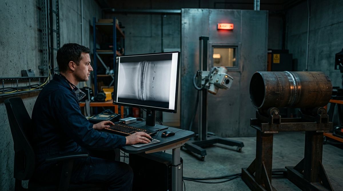
An industrial radiograph is not a photograph: it is an attenuation map that must be read methodically. The same dark indication can be a harmless pore, a slag inclusion at the edge of acceptability, or the start of a crack that condemns the joint. And before interpretation comes technique: a film exposed with the wrong geometry, or with the IQI badly placed, proves nothing — however "good" it looks. This article approaches radiographic testing from the applied side, through three cases: pipe butt welds, castings (sand and die cast), and exposure technique setup. For the comparison between technologies (film, CR, DR) see the dedicated guide industrial radiography: CR vs DR: here we discuss how radiography is used, not which system to buy.
The normative framework: who decides what is acceptable
For weld inspection the European normative chain has three levels, and it is worth having it clear before looking at any image. ISO 17636 (part 1 for film, part 2 for CR and DR) defines how to perform the radiograph: exposure geometries, technique classes A (basic) and B (improved), minimum distances, required IQIs. ISO 5817 defines the quality levels for imperfections of the welded joint: B the most stringent, C intermediate, D the least stringent. ISO 10675-1 is the bridge: it translates the quality levels into acceptance criteria for radiographic indications, with acceptance levels 1, 2 and 3 corresponding in general terms to B, C and D. For castings the logic is different, and we cover it in Case B: evaluation is by comparison with reference radiographs (ASTM E155, E505) following the general practice of ASTM E94. In both worlds, the sensitivity of the examination is demonstrated with image quality indicators (IQIs) of the ISO 19232 series.
Case A — Pipe butt welds: technique and exposure
Typical scenario: circumferential (girth) welds on power-plant piping or on a transmission line, diameters from 25 to 400 mm, wall thicknesses from 3 to 20 mm, TIG/stick or wire processes. The first decision is the exposure geometry, which ISO 17636 codifies in a few families:
- Single-wall single-image (SWSI) with internal panoramic source: the source sits at the pipe centre, the detector wraps the circumference outside: a single exposure covers the whole joint. It is the most productive technique wherever internal access exists (with crawlers on pipelines) and the best geometrically, because the beam crosses one wall, perpendicularly.
- SWSI with internal detector: external source and film/detector inside the pipe, in sectors: used when the source cannot be centred but internal access for the detector exists.
- Double-wall single-image (DWSI): for larger diameters (indicatively above 100 mm) without internal access: the source sits close to the wall, the beam crosses two walls but only the detector-side wall is interpreted. Several exposures are needed to cover the circumference: as an order of magnitude, at least three at 120 degrees, and in practice often more, depending on diameter and thickness.
- Double-wall double-image (DWDI), elliptical: for small diameters (indicatively up to 100 mm outside diameter and thin walls): the source is offset from the weld plane and the weld projects as an ellipse, with both walls interpretable in the same image; normally two exposures 90 degrees apart. If the ellipse does not separate (weld cap wide relative to the diameter), the superimposed DWDI technique is adopted, with at least three exposures at 120 degrees.
The second decision is the IQI: wire type (ISO 19232-1) or step/hole type (ISO 19232-2), placed as a rule on the source side, on the parent metal adjacent to the weld; if only detector-side placement is physically possible, it must be marked and the technique qualified accordingly. The tables of ISO 17636 set the essential wire that must be visible as a function of penetrated thickness and technique class: class B demands better sensitivity than class A, together with higher minimum densities and tighter geometries.
Case A — The defects and their radiographic appearance
| Defect | Radiographic appearance | Interpretation key |
|---|---|---|
| Porosity | Round, sharply defined dark spots, isolated or in groups (clusters, aligned) | Regular shape; the distribution (uniform, aligned at the root) points to the cause |
| Slag inclusions | Irregular, elongated dark indications, often in lines along the bevels between passes | Jagged outlines; typical of covered-electrode and submerged-arc processes |
| Lack of fusion | Thin dark line shifted towards the bevel face, often one-sided, slightly wavy | Position on the groove face; planar defect, visible only when nearly parallel to the beam |
| Lack of penetration | Continuous, straight dark line in the weld centre, at the root | Follows the joint axis; sharp edges of the unfused lands |
| Cracks | Very fine, jagged or branched dark lines, sometimes barely perceptible | Planar defect: detectability collapses if the plane is not aligned with the beam |
| Undercut | Irregular dark band along the outer edge of the weld cap | Correlate with visual examination of the external profile |
On the film (or digital image) the interpreter then applies the criterion: at ISO 10675-1 acceptance level 2 (the most common case, corresponding to ISO 5817 quality level C) porosity and slag are permitted within dimensional and cumulative limits, while cracks are never acceptable, at any level. The structural weak point of radiography remains orientation: a planar defect perpendicular to the beam can be invisible. That is why, on heavy sections and critical joints, radiography is complemented or replaced by ultrasonics: the full comparison is in industrial radiography vs ultrasonic testing.
Case B — Sand castings and die castings: the severity-grade logic
Second scenario: a sand-cast steel valve body and a die-cast aluminium automotive housing. The defects to look for change, and above all the way they are judged changes:
- Shrinkage: solidification cavities with jagged outlines, in the concentrated-cavity, spongy and filamentary/dendritic variants; it concentrates in heavy sections and thermal nodes of the casting.
- Gas porosity: round indications with sharp edges; in die castings it is the dominant defect, linked to air entrapped by the rapid filling of the die.
- Inclusions: sand or oxides dragged into the metal: they appear darker (less dense) or lighter (denser) than the matrix depending on their nature.
- Cold shut: a dark line with rounded edges where two metal fronts met without fusing; a close relative of incomplete filling (misrun).
Unlike welds, castings have no universal "level C": evaluation is done by comparison with reference radiographs. The ASTM E155 catalogue (aluminum and magnesium sand and permanent-mold castings) and ASTM E505 (aluminum and magnesium die castings) show each defect family at increasing severity grades; analogous ASTM catalogues exist for steel castings. The drawing or purchase specification states the maximum acceptable grade — often zone by zone: stringent on machined surfaces and pressure-retaining areas, more permissive in bulk material. The ASTM E94 practice serves as the general guide to radiographic quality. When the casting geometry makes the 2D projection ambiguous, or when porosity must be quantified in volume, the next step is tomography: see our guide to industrial CT scanning.
Case C — Technique setup: kV, screens, density and IQIs
Third case, common to the first two: the exposure technique. The points that decide image quality are few and must be governed together:
- Voltage (kV): more kV means more penetration but less contrast. The practical rule is to use the lowest kV compatible with the penetrated thickness and with reasonable exposure times; ISO 17636 publishes the maximum-voltage curves as a function of thickness and material. For the same thickness, aluminium requires far lower voltages than steel.
- Intensifying screens: with film, thin lead screens in contact are used, reinforcing the image and filtering scattered radiation; backscatter is controlled with rear shielding and checked with the classic lead letter "B" behind the cassette.
- Density (film): the optical density in the area of interest must be at least 2.0 in class A and 2.3 in class B, with an upper limit set by the viewer: outside this range perceived contrast collapses and the report is not valid.
- SNR and grey values (digital): in CR/DR the density criterion is replaced by normalized signal-to-noise requirements and correct use of the detector dynamic range, with calibration and bad-pixel correction; basic spatial resolution is verified with the duplex-wire IQI (ISO 19232-5). Panel selection criteria are in how to choose a DR detector for weld inspection.
- Geometry: source-to-object distance and focal spot size determine geometric unsharpness, i.e. sharpness: it is a chapter of its own, covered with formulas and worked cases in the X-ray tube in practice: focal spot and parameters.
Common errors that invalidate the report
- IQI placed on the detector side without marking or technique qualification: the declared sensitivity is not demonstrated.
- Density outside the range in the area of interest, or excessive gradient between weld centre and edges.
- Elliptical technique forced onto diameters or weld caps that are too large: the two walls overlap and interpretation becomes arbitrary.
- kV set too high "to be quicker": contrast flattens and fine porosity disappears.
- Too few exposures around the circumference: sectors remain with excessive penetrated thickness and out-of-spec sensitivity.
- Searching for cracks with an unfavourable beam orientation: the absence of indications does not prove the absence of the defect.
From the film to the decision: the next step
Setting up a radiographic examination properly means bringing together the applicable standard, the part geometry, the source, the detector and the acceptance criteria — and that work is best done starting from your actual joints and castings. PITECH supports Italian industry in the selection and supply of industrial radiography systems — generators, DR detectors, CR systems and accessories — with application evaluations on customer samples: describe your case via the contact page, by form, WhatsApp or email.
Frequently asked questions about weld and casting radiography
Which radiographic technique is used for small-diameter pipes?
For small diameters (indicatively up to 100 mm outside diameter and thin walls) the reference technique is double-wall double-image (DWDI) in elliptical projection: the source is offset from the weld plane, the weld projects as an ellipse, and normally two exposures are taken 90 degrees apart. Where the elliptical technique is not practicable (wide weld cap, unfavourable geometry) the superimposed DWDI technique is used instead, with at least three exposures 120 degrees apart, as provided by ISO 17636.
How do you tell lack of fusion from lack of penetration on a radiograph?
Lack of penetration appears as a continuous, straight dark line in the centre of the weld, at the unfused root; lack of fusion appears as a thin dark line shifted towards the bevel face, often on one side only and slightly wavy. The position relative to the weld axis, together with knowledge of the joint (bevel preparation, welding process), is the key to interpretation.
What is the relationship between ISO 10675-1 and ISO 5817?
ISO 5817 defines the quality levels for imperfections in welded joints (B the most stringent, C, D the least stringent) in metallurgical and dimensional terms. ISO 10675-1 translates those levels into acceptance criteria applicable to radiographic indications: acceptance levels 1, 2 and 3 correspond in general terms to quality levels B, C and D. The design or the construction code sets the required level; the interpreter applies it to the film or digital image.
Are casting radiographs evaluated the same way as weld radiographs?
No: castings are normally evaluated by comparison with reference radiographs. Catalogues such as ASTM E155 (aluminum and magnesium sand and permanent-mold castings) and ASTM E505 (aluminum and magnesium die castings) show each defect family at increasing severity grades; the drawing or specification states the maximum acceptable grade, often different from zone to zone of the casting. It is a grading logic, not a simple dimensional accept/reject.
When is it worth moving from film to CR or DR digital radiography?
When inspection volumes grow, when short cycle times, digital image traceability or assisted analysis are needed, and when the recurring costs of film and chemistry weigh on the operation. CR reuses much of the film workflow with phosphor imaging plates; DR with flat-panel detectors eliminates processing and enables near-real-time inspection. ISO 17636-2 governs the digital techniques with SNR and spatial-resolution requirements equivalent to the film classes.