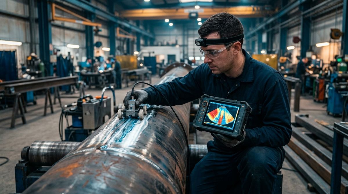
In conventional ultrasonic testing the operator sees a signal — the A-scan — and interprets it in real time, leaving no trace of what was seen. Phased array ultrasonic testing (PAUT) changes both things: it produces cross-sectional images of the material and records all the data together with probe position. That is why PAUT has become the de facto standard for critical weld inspection, corrosion mapping and complex components. This guide explains the principle clearly, lays out real advantages and limits, and gives the criteria to decide when moving up from conventional UT actually pays off.
The principle: many elements, one electronically controlled beam
A phased array probe contains many small piezoelectric elements — typically 16, 32, 64 or 128 — arranged in a linear (or matrix) array. Each element can be fired with an individual time delay. It is the same principle as wave interference: if the elements emit with suitably computed delays — the focal laws — the elementary wavefronts combine into an overall beam whose two key properties are controlled electronically:
- the propagation angle (beam steering): progressive delays along the array tilt the resulting wavefront;
- the focusing (beam focusing): parabolic delay profiles concentrate energy at a chosen depth, improving resolution and signal-to-noise ratio in that zone.
On reception the mirror process takes place: the signals from the individual elements are delayed and summed coherently. From this come the typical PAUT displays:
- S-scan (sectorial scan): the instrument electronically sweeps a range of angles (for example 40° to 70°) and composes a sector image of the part's cross-section: the colour "slice" that has become the symbol of phased array.
- E-scan (electronic or linear scan): the same group of focal laws is switched along the array, moving the beam electronically at constant angle: like sliding a conventional probe, without moving it.
- C-scan: pairing the probe with an encoded scanner, the data are mapped over the surface: the plan view used in corrosion mapping.
All of it remains classical ultrasound physics: reflection at interfaces, mode conversion, attenuation. Phased array does not change the physics: it changes beam control and the amount of information collected.
PAUT vs conventional UT: what really changes
| Aspect | Conventional UT | Phased array (PAUT) |
|---|---|---|
| Angular coverage | One angle per probe/wedge (45°, 60°, 70°) | Range of angles in a single pass (S-scan) |
| Data presentation | A-scan (signal), real-time interpretation | S-scan/E-scan/C-scan images + A-scan |
| Recording | Typically none (report only) | Full data with encoder position, re-analysable |
| Repeatability and audit | Operator-dependent | Encoded scan, comparable over time |
| Speed on welds | Multiple passes with multiple probes | One-two passes along the joint |
| Instrument cost and setup | Low | Higher; requires a scan plan and more elaborate calibration |
| Personnel | UT Level 2 per ISO 9712 | Specific phased array qualification |
The most underestimated difference is the last row: PAUT is not "UT with a colour screen". Without a correct scan plan (coverage of the weld volume, angles, focal laws, calibrations on blocks with known reflectors) the colour image only gives an illusion of completeness. Specific training and qualification of personnel are part of the real cost of adoption.
Where PAUT delivers the most
- Weld inspection: the flagship application. Butt welds on piping and pressure vessels, structural joints, fillet welds with limited access. The swept beam catches planar defects at different orientations — lack of side-wall fusion, lack of penetration, cracks — and the image makes depth and height sizing easier.
- Corrosion mapping: C-scan maps of remaining thickness on piping, shells and tank bottoms, with point density and productivity unthinkable with a spot thickness gauge; encoded maps are comparable between successive inspections to estimate corrosion rates.
- Composites: delaminations, porosity and inclusions in aerospace laminates, with 0° linear arrays with high element density.
- Complex geometries: bushings, shafts, blade roots, curved surfaces: where a conventional probe would need dedicated wedges for every angle, phased array adapts the beam in software (up to matrix probes for out-of-plane steering).
Worth mentioning in passing: on thick welds PAUT is often combined with TOFD on a single scanner in merged configurations; a comparative deep-dive is beyond the scope of this guide.
Real advantages and limits
Advantages: speed (fewer passes, more coverage), full data recording — meaning after-the-fact re-analysis, second opinions, end-client audits and historisation —, images that reduce interpretive ambiguity, better probability of detection on planar defects at any orientation, and the possibility, allowed by major construction codes, of replacing radiography on many welds: no radiation sources, no interruption of other site activities. For the comparison between radiographic and ultrasonic methods see industrial radiography vs ultrasonic testing.
Limits: higher initial investment (instrument, probes, scanners, software, training); dependence on the quality of the scan plan and calibrations; coupling to be ensured on irregular surfaces; coarse-grained, anisotropic materials (austenitic welds, Inconel) that skew and attenuate the beam and require dedicated transmit-receive longitudinal probes; and the fact that the image does not remove the need for competence: classifying indications remains a judgement for qualified Level 2/3 personnel.
The reference standards
- ISO 13588 — ultrasonic testing of welds using (semi-)automated phased array technology: testing levels, procedure and equipment requirements.
- ISO 20601 — phased array on thin-walled steel welds (typically from 6 mm): extends applicability where conventional UT is at its limit.
- ISO 18563 series — characterization and verification of phased array instruments, probes and systems: the basis for demonstrating that the measurement chain is under control.
- ASME BPVC Section V, Article 4 — ultrasonic examination for the American pressure vessel and piping codes, with the requirements for data-recording techniques.
- ISO 17640 — conventional ultrasonic testing of welds: the baseline reference when evaluating the move to phased array.
Practical note: acceptance of indications does not sit in these technique standards but in the criteria of the applicable construction code or design specification. Technique and criteria must always be declared together in the procedure.
How to choose a PAUT instrument
- Channel architecture: quoted as "active:total" (16:64, 32:128...). Active channels determine the usable aperture per focal law, total channels how many probes/elements you drive without external multiplexers. For standard welds 16:64 is often enough; high-density corrosion mapping and matrix probes ask for more.
- Probes and wedges: frequency (2-5 MHz typical on carbon steel, higher on thin sections and composites), element count and pitch, wedges for the required angular range, dedicated probes for attenuating materials.
- Scanners and encoders: encoded recording is what makes the data defensible: evaluate scanners for piping (magnetic chains, bands), for flat surfaces, and their fit to the real diameters of the asset base to inspect.
- Software: scan-plan building with coverage simulation, guided calibrations (TCG/DAC), analysis and reporting, data export in re-readable formats: in PAUT the software weighs as much as the hardware.
- TFM/FMC evolution: many current instruments also offer the Total Focusing Method on Full Matrix Capture acquisition (public reference: ISO 23865), with focusing at every point of the region of interest: useful on fine defects, worth evaluating for future use.
- Ergonomics and site work: weight, battery life, sunlight readability, IP robustness, file management: an 8-hour inspection at height is judged on these too.
When the move from UT to PAUT pays off
The move pays off when at least one of these conditions is true: inspections are recurring and volumes justify the higher productivity; the client or the code requires recorded, traceable data; geometries would multiply the conventional probes needed; radiography must be replaced for safety or site-continuity reasons; or corrosion mapping must produce maps comparable over time. It does not pay off — or not yet — when inspections are occasional, geometries simple and nobody asks for recorded data: in that case the cost of instrument, training and qualification does not repay itself.
A correct evaluation starts from the application, not from the price list: joints or components to inspect, thicknesses and materials, expected defects, acceptance criteria, annual volumes. On that basis, configuration (channels, probes, scanners) and procedure are defined and tested on the real part. PITECH supports this evaluation neutrally within its industrial ultrasonic testing PAUT/TOFD solutions: describe your application via the contact page.
Frequently asked questions about phased array ultrasonic testing (PAUT)
What is phased array ultrasonic testing (PAUT)?
PAUT is a non-destructive testing technique that uses probes made of many piezoelectric elements (typically 16, 32, 64 or more). By firing the elements with computed time delays (focal laws), the ultrasonic beam is steered and focused electronically without moving the probe. The result is a cross-sectional image of the material (S-scan, E-scan) instead of the single A-scan signal of conventional UT.
What is the difference between PAUT and conventional ultrasonic testing?
A conventional UT probe has a single element and one angle per wedge: covering a weld requires several probes and several passes. PAUT covers a range of angles (for example 40-70°) in a single pass, produces cross-sectional images that are easier to interpret, records all data with encoder position and makes the inspection repeatable and auditable. In exchange it requires more expensive instruments, more elaborate calibration and specifically qualified personnel.
Which standards govern PAUT weld inspection?
The main references are ISO 13588 (ultrasonic testing of welds using automated or semi-automated phased array technology), ISO 20601 (phased array on thin-walled steel welds), the ISO 18563 series for equipment characterization and verification and, in the American code framework, ASME BPVC Section V, Article 4. Personnel qualification follows ISO 9712.
Can PAUT replace radiography on welds?
In many cases yes: major construction codes allow advanced ultrasonic examination with data recording as an alternative to radiography, with advantages in safety (no radiation source), uninterrupted site work and sensitivity to planar defects such as lack of fusion. Radiography remains preferable or complementary for certain volumetric defects, geometries and materials: the choice must be based on expected defects, thicknesses, access and the applicable code requirements.
When is it worth moving from conventional UT to PAUT?
When inspection volumes are recurring (production or site welds, corrosion mapping on large assets), when the end client or the code requires recorded, traceable data, when complex geometries would require too many conventional probes, or when speed and probability of detection must increase. For occasional spot checks on simple geometries, conventional UT often remains the most economical choice.