Custom • 2D radioscopy • 3D computed tomography

Custom industrial CT systems: 2D radioscopy and 3D computed tomography.

Two CT scanners with the same name can give very different results on the same casting, because resolution depends on the part more than on the datasheet. That is why PITECH configures 2D digital radioscopy and 3D CT systems starting from your parts, for the quality lab or the production line.

Custom systems

How a custom CT system is put together.

Each block has several options, and the proposal gives the reason for every choice.

Why a custom system with PITECH

Sized on your most difficult part.

Custom systems2D radioscopy and 3D CT configured by PITECH Industrial Solution around the part and the application

The system is sized on the part that is most critical for detail and on the bulkiest one, with a margin for the part numbers still to come. You do not pay for performance you will never use, and you do not run into a limit after installation.

Configured around the part

Source, detector and manipulator are chosen together, because focal spot, pixel size and magnification set the voxel size only in combination.

A trial before the decision

A scan of your part checks, before the order, that the defect or dimension to be inspected is actually visible.

2D and 3D when you need both

Radioscopy for screening and CT on doubtful parts can share the same machine.

System or service

With few parts the contract CT scanning service may be enough, and the data it produces later help size the system.

Custom systems / Configurations

Six building blocks, one configuration.

The sheets give qualitative values: tube voltage, power, detector format, travel and cabinet are fixed in the proposal, on your part.

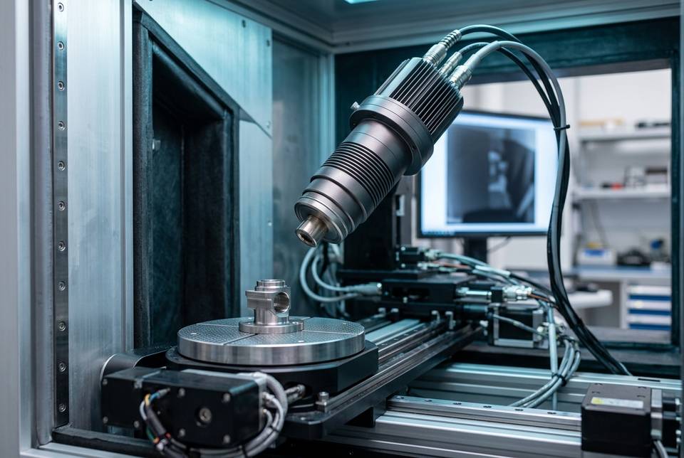
Microfocus X-ray tube inside an inspection cabinet, aimed at a part on the rotary table
X-ray source • Energy and focal spot

X-ray source: microfocus, minifocus, high energy

The source decides how much material can be penetrated and how small a detail can be resolved, and the two pull in opposite directions: with the same technology the focal spot grows with power, so the energy needed to get through a steel casting is paid for in sharpness at high magnification. The compromise is found on the real part.

OptionWhen to choose itNotes
Open-tube microfocusFinest detail on small parts, electronics, plastics, light alloys, additive partsPeriodic filament and vacuum maintenance; limited power
Sealed-tube microfocusSame applications, simpler handlingNo vacuum maintenance; focal spot not adjustable
MinifocusMedium-sized castings and componentsMore power, at the expense of the smallest detail
High energyLarge steel and cast-iron castings, thick sectionsHigh tube voltages or linear accelerators; dedicated shielding and space
Voltage, power, focal spotConfigurableSet in the proposal on the most critical part
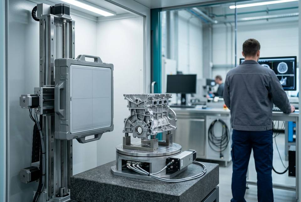
Flat panel digital detector on a vertical linear axis in a CT system, with a casting on the rotary table
Detector • Resolution and field of view

Flat panel detector

Detector pixel size and format decide, together with magnification, the achievable voxel size and how much of the part fits in a single acquisition: when the part fills the detector, the voxel is roughly the imaged diameter divided by the number of pixels. Dynamic range decides whether thin walls and heavy sections stay readable in the same image.

OptionEffectNotes
Fine-pixel flat panelMore detail at the same magnificationSmaller field of view
Large-format flat panelLarge parts in a single projectionFewer stitched acquisitions
High dynamic rangeVery different thicknesses in the same imageUseful on castings with thin walls and heavy sections
Line detector (fan-beam)Less scattered radiation on large, dense partsSlower scan; examination per ASTM E1570
Pixel size, format, speedConfigurableChosen on required resolution and cycle time
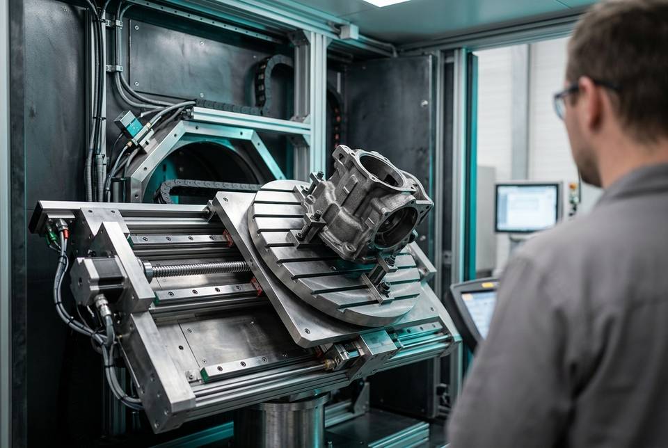
Multi-axis manipulator with rotary table, linear guides and ball screws holding a casting in a CT cabinet
Mechanics • Axes and cabinet

Manipulator, axes and cabinet

Moving the part towards the source increases magnification; rotation is what CT needs, while translations and tilt frame the critical zones in 2D. Load capacity, travel and cabinet follow the largest and heaviest part, with a margin for fixtures.

ElementOptionsNotes
Rotation axisPrecision rotary stageIts stability affects volume quality
TranslationsMovement towards the source, vertical and lateral travelSet magnification and framing
TiltOblique views in 2DUseful on welds and complex geometry
Load capacity and travelConfigurableSized on maximum weight and envelope
CabinetShielded, sized on the inspection envelopeFor high energies, a bunker or shielded room
AccessFront door, top loading, pass-through for the lineChosen on the part flow
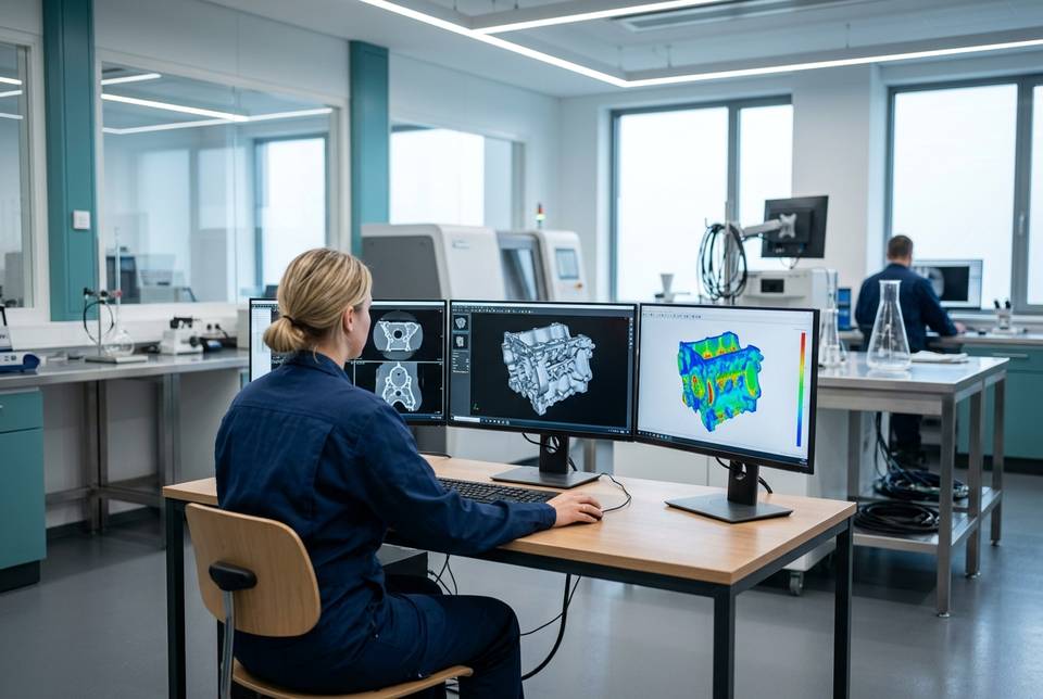
CT analysis workstation with 3D volume, slices and wall-thickness map on three monitors
Software • Reconstruction, analysis, ADR

Software: reconstruction, defect analysis, metrology and ADR

On the same volume, two segmentation methods can give different porosity percentages: software affects the result as much as the machine. It has to be chosen on the inspection goals, because defect analysis and metrology call for different modules and different verification.

ModuleFunctionNotes
Acquisition and reconstruction3D volume from projections, artefact correctionConfigurable trajectories, including helical for long parts
Defect and porosity analysisSegmentation, pore volume and position, percentage by zoneMeasurement conditions can be documented in the report
Metrology and CAD comparisonNominal/actual comparison, dimensions, wall thicknessAccuracy to be verified with acceptance tests (VDI/VDE 2630)
ADRAutomatic defect recognition on inline 2D imagesReject criterion validated on sample parts
Reporting and traceabilityReports, image archive, data exchangeStandard formats such as DICONDE (ASTM E2339)
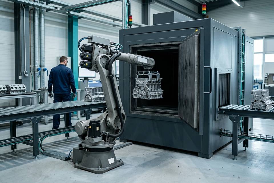
In-line X-ray cell in a foundry: a fixed industrial robot loads an aluminium casting from the conveyor into the shielded cabinet
Options • Production

Automation, inline version, 2D + 3D

With these options a lab system becomes a production inspection station, and cycle time joins the requirements for source and detector.

OptionWhen you need itNotes
Automatic or robot loadingRepetitive volumes, shifts without continuous attendanceGripping fixtures designed on the part
Inline version100% inspection or extended samplingCycle time and reject criterion defined before the project
2D + 3D in the same systemFast screening and CT on doubtful partsSource and detector chosen for both modes
Helical scanningLong or tall partsConfigurable
Additional analysis workstationsSeveral operators on the same dataSoftware licences to be sized
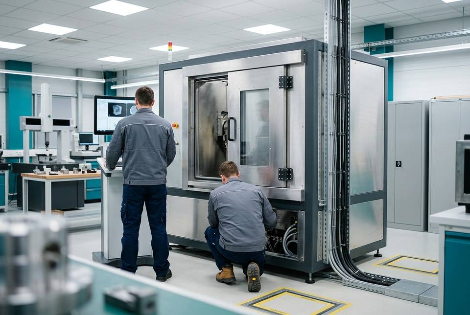
Technicians commissioning a newly installed shielded CT cabinet in a factory
Services • From order to use

Installation, radiation protection, training and support

A CT system enters the shop floor after a few checks that belong before the order: space, floor load capacity for the cabinet weight, power supply, delivery route. Radiation protection is a user requirement: in Italy it derives from Legislative Decree 101 of 31 July 2020 implementing Directive 2013/59/Euratom, and it is defined case by case with the radiation protection expert appointed by the company.

PhaseWhat it includesNotes
Preliminary checksSpace, floor, power supply, accessBefore the final offer
Installation and commissioningPlacement, functional acceptance, tests on the customer's partsCoordinated by PITECH
Radiation protectionUser obligations under Legislative Decree 101/2020Based on the system's technical documentation
TrainingUse of system and software, scan set-upFor operators and quality managers
Support and spare partsTechnical support, maintenance, software updatesWith PITECH as the contact

A configuration proposed on your part

Describe your parts and the detail to detect, and we will propose a 2D, 3D or combined configuration. Quote within 24 hours.

  • Every choice explained in the proposal
  • 2D radioscopy and 3D CT
  • Trial scan can be arranged
2D or 3D

2D radioscopy, 3D CT or both.

The first choice is the kind of answer you need. If the critical defect shows up in projection and cycle time matters, 2D radioscopy is almost always enough; if you need depth, the real size of the defect or internal dimensions, you need the 3D volume.

Comparison between 2D digital radioscopy, 3D computed tomography and a combined 2D + 3D system
ModeWhat it returnsTimeWhen to choose it
2D radioscopyReal-time projection, defects visible in projectionA few seconds per viewSeries parts, inline inspection, automatic recognition
3D CTVolume with defect position and size, internal and external dimensionsMinutes to hours per scanDefect analysis, metrology, first article qualification
2D + 3D system2D screening and 3D analysis of doubtful partsDepends on the part mixWhen you need both answers on the same flow

For series inspection see real-time radioscopy on the industrial radiography page and the article on when industrial radioscopy pays off. System families and technical criteria are on the industrial computed tomography page.

How we configure the system

From the part to the offer, in four steps.

The first quote arrives within 24 hours; the final offer follows the sample-part trial, when one is planned.

1. Part and requirements analysis

We start from the toughest requirement, the tightest tolerance or the smallest defect, and from your customer's specifications.

2. Configuration proposal

Each component with the reason for the choice and the limits to be aware of.

3. Sample-part trial

Scan of the sample part with the proposed configuration.

4. Offer

Final configuration, installation, training and support in a single offer, with no items left to clarify after the order.

What to send us to start

Drawing or photo of the part, material, size and weight, defects or dimensions to check, volumes and cycle time.

After the order

Commissioning with tests on your parts, then the same contact for support and spare parts.

Applications

Where CT systems are installed.

Foundry and die castingAutomotiveAerospaceElectronicsPlastics and mouldingAdditive manufacturingBattery cells and modulesQuality and R&D labs
System or service

When an in-house system pays off.

An in-house CT scanner pays for itself with routine scans on the same part family, with turnaround that weighs on production, or if product data must not leave the company. With a few parts a year or occasional problems the service usually remains the more sensible choice.

PITECH also offers the contract CT scanning service. The costs a machine quote does not show, from the cabinet to radiation protection, are discussed in industrial CT, buying a system or using a service.

FAQ

Frequently asked questions about custom industrial CT systems

What is the difference between a 2D radioscopy system and a 3D CT scanner?

Radioscopy projects the part onto the detector in real time and overlaps everything the beam passes through in a single image, so it cannot tell how deep a defect lies. CT reconstructs a volume from hundreds of projections acquired while the part rotates: it gives the position and size of defects and the dimensions of the part, with longer scans.

How accurate is an industrial CT scanner?

There is no single figure: the error depends on the measurement task, the material and how the part sits in the volume. System performance is verified with the acceptance tests of VDI/VDE 2630 Part 1.3, which brings the ISO 10360 approach to CT, and for critical dimensions the uncertainty is determined according to Part 2.1.

Can a CT or radioscopy system work inline?

Yes, and cycle time decides how. 2D radioscopy with automatic defect recognition fits inline more easily; inline CT accepts a coarser voxel size to stay within the cycle, or is reserved for the parts radioscopy flags as doubtful.

Do you need a bunker to install an industrial CT scanner?

For cabinet systems, usually not: the shielded cabinet contains the radiation and the system is installed on the shop floor. A bunker or shielded room is needed with high-energy sources and linear accelerators. In both cases the assessment rests with the radiation protection expert appointed by the company, under Italian Legislative Decree 101/2020.

Which part should you use for the trial scan?

The most difficult one you have: the thickest or densest, the one with the smallest defect to find, or better still a part your customer has already rejected. If the configuration sees the defect there, it will see it on the others, while an easy part proves little.

Application support

From installation to production.

Before the system is trusted with decisions, it has to be shown to measure and reject as intended, on your parts.

Acceptance tests

Accuracy verified on the measurement tasks that matter to you, with reference to VDI/VDE 2630.

Reject criterion validation

The automatic recognition reject criterion tested on good and defective parts before inline use.

Training

Use of the system and software, with support during the first scans.

Contact

Request a quote for a custom CT system.

Describe the parts to be inspected: PITECH Industrial Solution replies with a configuration and the quote.

Application request

Tell us about the industrial project to evaluate.

WhatsApp