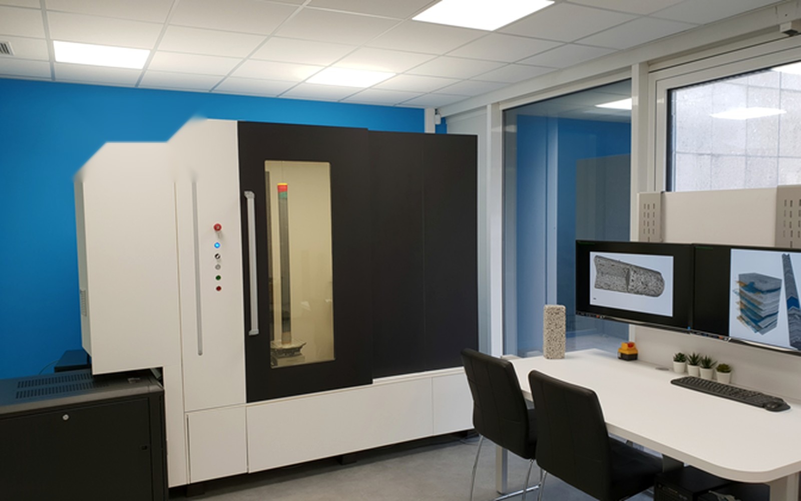
In an alloy wheel foundry, the X-ray check takes as long as the wheel's trip through the cabinet. The manipulator grips it, spins it and tilts it in front of the beam while images scroll across the monitor, and before the next wheel arrives the part is already on the conforming conveyor or on the reject line. No films to develop, no plates to scan: this is industrial radioscopy, radiography in real time.
Quality managers in foundries, or in shops that weld in batches, hear it pitched every time volumes grow. It pays off when the part repeats, when inspection has to fit inside the line's cycle time and when the critical defects show up in an image acquired in a few seconds. Outside that envelope, static radiography and CT remain the better choices, and it's worth knowing that before ordering a cabinet.
What happens inside a radioscopy cabinet
There are four building blocks. The X-ray tube, often with a small focal spot, sets energy and sharpness; the detector turns X-rays into images at tens of frames per second; the manipulator brings the part into each viewing position; the self-shielded cabinet holds everything and protects the people outside. The old image intensifier with a camera, which distorted the edges, has largely given way to flat panels, the same digital detector arrays (DDAs) used in digital radiography.
The manipulator is the part catalogues say least about. With linear axes, rotation and tilt, the part meets the beam at the right angle: a crack whose plane is parallel to the beam shows up, while the same crack turned ninety degrees can vanish. Geometry also sets magnification, the ratio of source-to-detector to source-to-object distance, and with it geometric unsharpness, which grows with focal spot size multiplied by magnification minus one. That's why high magnification calls for minifocus or microfocus tubes, as our article on how to choose an X-ray tube and generator explains.
There's also a trade-off static radiography never faces. A single frame is noisy; averaging N frames improves signal-to-noise roughly with the square root of N, because quantum noise follows Poisson statistics, but the part has to stop and the cycle gets longer. ASTM E1255-23 accordingly separates dynamic examination, with the object moving, from static examination. On the line the two alternate: move to search, stop and integrate to decide.
Radioscopy, radiography and CT answer different questions
All three use the same X-rays, but they deliver different data in different times.
| Criterion | Radiography (film, CR, static DR) | Radioscopy | CT |
|---|---|---|---|
| Output | One 2D projection per exposure | Sequences of 2D projections from several angles | A reconstructed 3D volume |
| Time per part | Minutes, plus processing or scanning for film and CR | Seconds per view | Minutes to hours |
| Defect depth | Not available from a single exposure | Estimated by rotating the part | Measurable, with position and volume |
| 100% in-line inspection | Rarely sustainable | Yes, if cycle time and views allow | Usually sampling |
The comparison points one way. With a series part, a critical defect visible in projection and a cycle time to meet, radioscopy is almost always the right technique, and static radiography becomes a cost that grows with volume. If you need the pore's position and volume or an internal dimension, you have to move to industrial computed tomography, which rarely holds up on every part: 3D data costs time and needs explicit counting rules, as our articles on CT porosity measurement in castings and on two labs reporting two porosity values for the same casting show. Classic radiography, on film or along the two digital routes in CR versus DR, stays the answer for one-off parts, field work and specifications that call for it; our industrial radiography equipment page covers the options.
Aluminium castings, wheels, welds: where radioscopy pays back
The natural home is the light-alloy foundry. In aluminium die castings and permanent-mould castings, gas porosity, shrinkage, inclusions and oxides show good contrast against a weakly absorbing matrix, and parts repeat by the thousand. Alloy wheels are the textbook case: rotational symmetry, known critical zones across spokes, rim and hub, a few programmed views. Here 100% in-line inspection replaces sampling, and the difference shows on sporadic defects. A plan that checks one casting in fifty lets forty-nine parts through unseen, by design.
Welds produced in series, on automotive components, gas cylinders or heat exchangers built in batches, follow the same logic. For radioscopic examination, ASTM E1416-23 sets the image quality requirements; with digital detectors in static imaging, ISO 17636-2:2022 applies and calls for detection sensitivity equivalent to film. Electronics works at low energies with microfocus tubes, looking for voids in ball-grid solder joints. In aerospace, radioscopy comes in only where the customer specification allows it, which is worth checking before investing.
The flip side is just as clear. Large, heavy parts made in small numbers, with steel sections that need high energies, stay with static radiography or an outside lab. And tight cracks not aligned with the beam can escape an image acquired in a few seconds even when a long exposure would reveal them.
Do you have castings or components to inspect in series?
Send us a drawing or photo of the part, material, wall thicknesses and volumes: we'll tell you whether radioscopy pays off and which configuration you need. Quote in 24 hours.
Email us Message us on WhatsAppThe standards that set image quality, and the ones that don't decide rejection
A radioscopy specification works on two levels, system quality and the acceptance criterion for the part. Standards cover the first well and the second hardly at all.
| Standard | Family | What it covers |
|---|---|---|
| EN 13068-1:1999 | Technique, system qualification | Measurement of the system's imaging properties on a test specimen, in the laboratory; moving conditions excluded |
| EN 13068-2:1999 | Technique, stability | Routine checks with image quality indicators that operators can run on the installation in use |
| EN 13068-3:2001 | Technique | General principles for metallic materials; no acceptance criteria |
| EN 12681-2:2017 | Technique, castings | Castings with CR and DDAs; besides classes A and B, classes AA and BA for automated or semi-automated systems with computer-based flaw recognition and focal spots up to 1 mm |
| ASTM E1734-23 | Technique, castings | Image evaluated on a monitor, static or dynamic; fully automated evaluation excluded |
| ASTM E2698-26 with E2737-23 | Technique, DDAs | Examination with digital detector arrays; they shall be used together, the second for baseline and long-term stability |
| ASTM E505-22 and E155-20 | Acceptance reference | Reference radiographs for aluminium and magnesium die castings and castings, with increasing severity levels |
One rule follows, and buyers need it before the quotation. The acceptable severity level is set by the customer or the drawing, and reference radiographs give that level a shared name, as happens for welds in our article on who decides acceptance levels. The E155-20 films, the standard itself warns, aren't intended for digital images, and for aluminium it points to the ASTM E2422 digital reference images. Two limits then weigh on acceptance testing: EN 13068-1:1999 measures performance with the part at rest, while on the line what counts is performance in motion, and ASTM E2737-23 is a user practice that states it isn't an acceptance test of the supply. If you want a contractual acceptance test, write it into the order, with the parts and images it will be judged on.
Automatic defect recognition: who answers when the software decides
When an algorithm makes the reject call, responsibility stays with the company running the inspection and the customer accepting it. The practice standards say so in their own way: ASTM E1734-23 for castings and ASTM E1416-23 for welds apply only to evaluation on a monitor and exclude systems in which the computer decides, while EN 12681-2:2017 qualifies the image of automated systems, not the algorithm's decision.
ADR (automatic defect recognition) promises decisions that repeat across shifts, no drop in attention and evaluation times that keep pace with the line. Domingo Mery's review in Materials Evaluation (2006) describes the classic pipeline: segmentation of potential defects, classification that separates them from the casting's regular structures, and tracking across several views to weed out false alarms. In 2018 Ferguson, Ak, Lee and Law, working between NIST and Stanford, published in Smart and Sustainable Manufacturing Systems a neural network trained on castings from the public GDXray database, beating earlier results on that data; GDXray holds 19,407 X-ray images and is described by Mery and colleagues in the Journal of Nondestructive Evaluation (2015). On a different casting, with another alloy and another tube, that model has to be retrained and re-verified, and the GDXray licence rules out commercial use anyway.
Validating ADR means measuring its probability of detection (POD) on your own parts. ASTM E2862-23 deals precisely with the hit/miss data of an accept/reject system and sets two preconditions: the discontinuity of interest defined up front, and a flaw-size distribution that is known and documented. MIL-HDBK-1823A, the aerospace reference for POD curves with 95% confidence bounds, remains guidance and can't be cited as a contractual requirement. In practice you need parts with known defects, confirmed by CT or sectioning, enough good parts to measure false rejects, a blind trial against an operator certified to ISO 9712:2021 and change control, because every retraining reopens validation. False rejects count as much as missed defects: each good casting scrapped costs a pour, and a high rate pushes operators to recheck everything by hand.
Cost per part is decided by cycle time
The price of a cabinet says little about the cost of inspection, which depends on how many parts go through per shift and how much human attention each one absorbs. Take an example built on our own assumptions: a casting with 10 views, 2 seconds of dwell and integration per view, about 1 second of travel between views and 15 seconds for loading and unloading occupies the cabinet for about 45 seconds. With a line turning out a part every 30 seconds, 100% inspection won't hold, and you need fewer views, a second cabinet or automatic loading that overlaps the phases.
Cutting views is the cheapest lever, provided sample parts prove the critical zones stay covered; ASTM E1734-23 itself asks users to consider areas the casting geometry keeps out of view. With monitor evaluation the operator looks at every part and attention fades over the shift; with validated ADR the operator looks only at suspects, and cost moves to validation. At low, irregular volumes the arithmetic flips, and an outside lab or static digital radiography often costs less than a dedicated cabinet, as our industrial radiography buying guide shows.
Who signs off before installation: radiation protection, space, power
The first signature belongs to the employer, and in Italy it comes before delivery. Legislative Decree no. 101 of 31 July 2020, which transposes Directive 2013/59/Euratom, requires the employer to ensure physical surveillance through a radiation protection expert (art. 128), who reviews the installation design in advance and carries out its first verification. Machines in which the maximum energy of accelerated particles exceeds 200 keV need prior authorisation (nulla osta, art. 50); the others, unless exempt, must be notified at least thirty days before start-up (art. 46). A 160 kV cabinet and a 225 kV cabinet can therefore face very different approval paths, even when the shielding is built in.
Physical constraints are often discovered late. Lead makes the cabinet very heavy and the floor has to be checked for concentrated load; door and usable volume must take the largest part with its fixture, and the manipulator must carry the weight with margin. Tube and generator normally need a three-phase supply and cooling, and the detector works best at a stable temperature.
Three mistakes you pay for after acceptance
The costliest mistakes share one root: a configuration chosen from the catalogue before anyone looked at the part. The first is a cabinet sized for the average part, where the largest casting doesn't fit with its fixture, or fits but the manipulator can't tilt it far enough to see the critical zone.
The second is too little voltage for the thickest section. The tube barely gets through the heaviest wall, long integration is needed for a clean image and the cycle time collapses. Energy, filtration and detector dynamic range have to be tested on real parts, not least because energy constrains the detector and ASTM E2698-26 warns that some of its tests may not apply above 450 kV; the topic continues in how to choose a DR detector. The third is ADR switched on as a catalogue feature, without validation: it works in the demo, then on a new casting it rejects too much or, worse, too little, and nobody has the data to say which is happening.
How to set up a feasibility test on your parts
A serious test starts from the parts: representative samples, including some with known defects; the list of critical defects with type, minimum size and location; the line's cycle time; the acceptance criterion, with the name of whoever sets it and the images used to judge. What comes out is a set of trial images on the programmed views, a cycle-time estimate and the minimum configuration of tube, detector, manipulator and cabinet.
The exit condition works both ways. If the critical defects show up repeatably within the cycle time, you move on to configuration and quotation. If they show up only with long integration, or not at all, 100% radioscopy isn't the answer, and you look at static digital radiography on a sampling basis or CT on critical batches.
What to send us for an evaluation
To tell you whether radioscopy pays off and which configuration you need, a few precise data points are enough:
- drawing or photo of the part, with envelope and weight, including the fixture;
- material or alloy, minimum and maximum wall thicknesses in the zones to inspect;
- critical defects: type, minimum size to detect and zones of the part;
- annual or per-shift volumes and the line's cycle time;
- acceptance criterion or customer specification, with reference images;
- current inspection: in-house radiography, outside lab or none;
- availability of sample parts, good and defective.
You can send them by email to info@pitech-solution.com or on WhatsApp, attaching drawings or photos.
The criterion to keep is simple. Radioscopy pays off when a repetitive part, a defect visible in projection and a cycle time all line up, and when whoever signs acceptance has already chosen the images parts will be judged on. If your parts sit in that zone, the next step is an evaluation on real samples, with a tailored quote in 24 hours; the case studies on welds and castings help decide where to start.
Frequently asked questions about industrial radioscopy
What is the difference between radioscopy and industrial radiography?
Radioscopy produces real-time images on a monitor while the part moves or dwells in front of the beam; radiography records one static image per exposure, on film, a CR plate or a DR panel. The first suits series inspection within cycle time, the second one-off parts, field work and specifications that mandate it.
When does radioscopy pay off over CT?
It pays off when seeing the defect in projection is enough and every part has to be checked in line. CT reconstructs the volume and measures pore position and size, but takes far longer and is usually applied to samples, prototypes or failure analysis.
Which standards apply to industrial radioscopy?
For the system, the EN 13068 series (parts 1 and 2 of 1999, part 3 of 2001); for castings, EN 12681-2:2017 and ASTM E1734-23; for welds, ASTM E1416-23 and, with digital detectors in static imaging, ISO 17636-2:2022; for DDAs, ASTM E2698-26 together with E2737-23. Acceptance levels are set by the customer or the drawing, often referring to the ASTM E505-22 or E155-20 reference radiographs.
Is automatic defect recognition (ADR) reliable?
It can be, if validated on your own parts. The ASTM practices for castings and welds exclude fully automated evaluation, so the proof falls to the user: probability of detection measured on known defects per ASTM E2862-23, the false-reject rate, and revalidation every time the model is retrained.
Do you need authorisation to install a radioscopy cabinet in Italy?
It depends on energy. Under Legislative Decree 101/2020, machines in which the maximum energy of accelerated particles exceeds 200 keV need prior authorisation (art. 50), while the others, unless exempt, must be notified at least 30 days before start-up (art. 46); in every case the employer must appoint a radiation protection expert (art. 128).
How much does an industrial radioscopy system cost?
It depends on part size and weight, tube voltage, detector, manipulator axes, loading automation and software, so a generic price would be misleading. PITECH prepares a tailored quote within 24 hours from a drawing or photo of the part, material, wall thicknesses and volumes, sent by email, WhatsApp or form.