CT Service • Contract industrial CT • 3D analysis

Industrial CT scanning service: contract CT analysis and inspection.

A pore under a sealing face, a dimension inside a channel no probe can reach: CT finds them without cutting the part. The PITECH CT scanning service handles small components and large castings, in metal, plastics and composites, with a report, a 3D volume or STL files depending on what you will do with the result.

CT Service

The analyses in our industrial CT scanning service.

Start from the problem you have. If the part needs several analyses, they all come from the same scan.

Why the CT service with PITECH

It starts with what you need to know.

Service: CT ServiceContract CT analysis by PITECH Industrial Solution for companies in Italy and across Europe

Voxel size, energy and part orientation are chosen for the defect or dimension you care about. If radiography or a cheaper inspection answers the same question, we tell you before quoting.

Assessment before the quote

Material, size and the smallest detail to detect tell us whether CT can reach what you need, before you commit to anything.

One contact from request to report

The same person agrees the analysis, arranges shipping and discusses the results with your engineers.

Comparable numbers

Voxel size, segmentation and analysed region are written in the report, so porosity stays comparable with later inspections.

Industry standards

ASTM E1441 and E1570, ISO 15708, VDI/VDE 2630: current editions are listed further down.

Confidentiality

NDA on request, signed before parts, drawings or CAD leave your company.

Service or system, same contact

PITECH also supplies custom industrial CT systems, in 2D and 3D, for when scanning becomes a daily task.

CT Service / CT analysis

Six analyses, one 3D volume to start from.

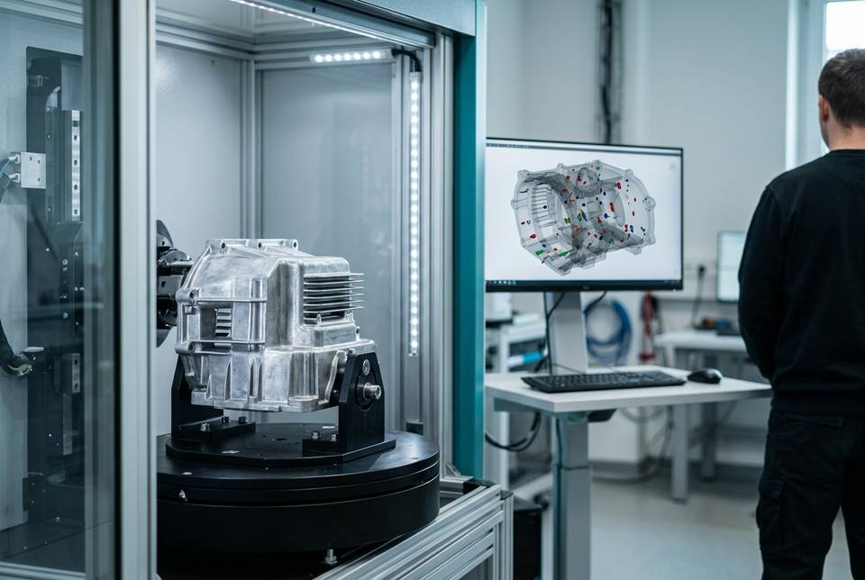
Every scan produces a volume of voxels, the small cubes that play the role of pixels in 3D; the analyses differ in what they extract from it.

Aluminium casting on the rotary stage of an industrial CT scanner, with the 3D volume and colour-coded pores on the monitor
Defect analysis • Volume

Porosity, voids, inclusions and cracks

Most of the work is aluminium castings, die castings, welds and mouldings. For every pore the scan also gives the distance from machined or sealing surfaces: under a seal seat a pore can cause a leak, in the middle of a rib it often does not matter, and the percentage alone cannot tell the two apart. Cracks show up when their opening is comparable to the voxel size; very tight ones can be missed, which is worth knowing before scanning.

FeatureDetail
Defects detectedGas and shrinkage porosity, voids, sink cavities, inclusions, open cracks
Data per defectVolume, equivalent diameter, 3D position, distance from the surface
Overall resultPorosity percentage over the region of interest, distribution by size class
Minimum sizeReliable from about 3–5 voxels per side
Stated conditionsVoxel size, segmentation method and threshold, analysed region
Acceptance criterionPorosity key on the drawing or the customer's specification
What you receiveReport with sections and a 3D pore map, defect table, volume video

Why two reports on the same casting can disagree is told in the case of two labs and two porosity percentages; for castings, see also porosity in castings and die castings with CT.

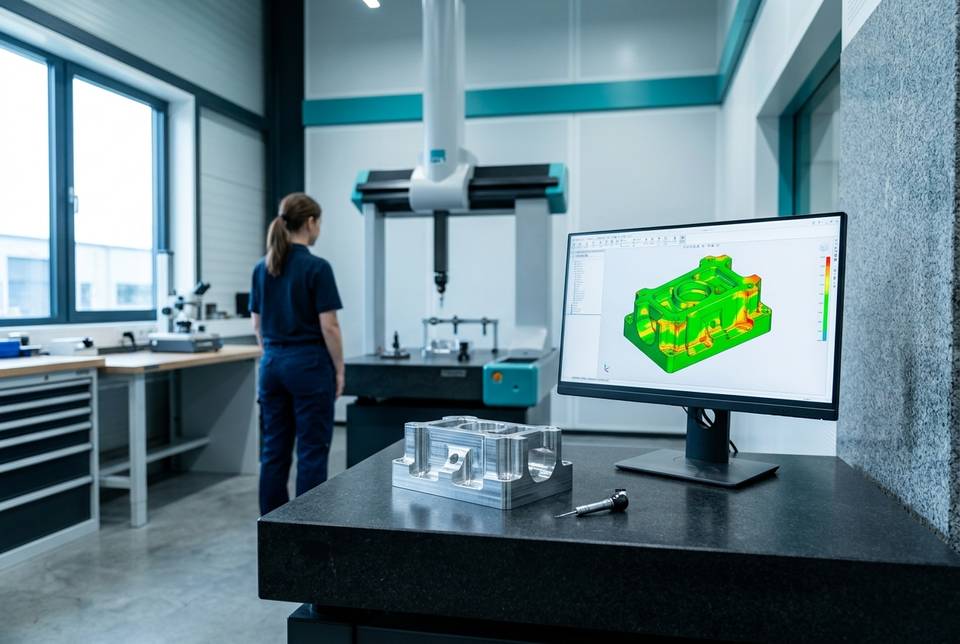
Precision machined part next to the colour map of deviations from the CAD model
Metrology • CAD comparison • FAI

Dimensional metrology, CAD comparison, wall thickness and first article

The surface extracted from the volume is aligned to the nominal CAD, and the colour map shows where the part has extra or missing material. For first article inspection (FAI), external and internal features come out of the same scan, channels included.

FeatureDetail
AnalysisNominal/actual comparison, dimensions and geometric tolerances, wall thickness, first article
Measurable featuresExternal and internal: channels, cavities, undercuts, surfaces a probe cannot reach
What we need from youNominal CAD model (STEP or equivalent format) and a drawing with the tolerances to verify
UncertaintyStated for the dimensions that decide the part, per VDI/VDE 2630 and ISO 10360 applied to CT
What you receiveDeviation map with tolerance scale, table of measured vs nominal dimensions, thickness map, PDF report

For CT measurement uncertainty and the comparison with a tactile CMM, see the article on CT metrology of internal geometry.

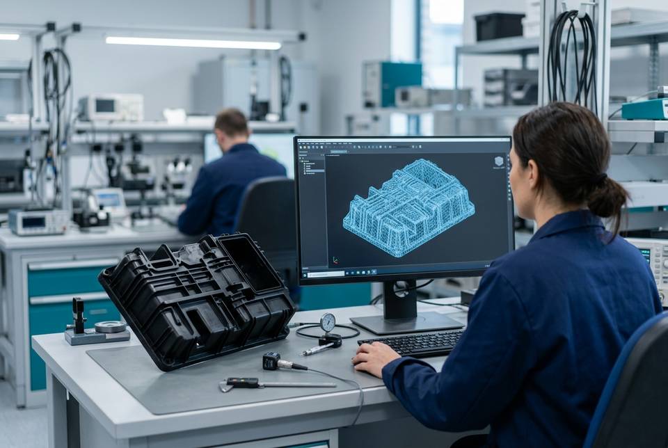
Moulded plastic housing next to its triangulated mesh obtained from CT for reverse engineering
Reverse engineering • STL / mesh

Reverse engineering and STL/mesh export

When the CAD has been lost, or never existed for a spare part, the surface extracted from the volume becomes an STL mesh with external and internal geometry in one file. Fidelity follows the voxel size and the quality of the surface determination; on multi-material parts, separate surfaces are extracted.

FeatureDetail
FormatSTL (triangulated mesh); other mesh formats by agreement
GeometryExternal and internal in a single scan, including channels and closed cavities
Typical usesModel reconstruction, spare parts with no drawing, simulation, comparison between part versions
FidelityEstimated during the assessment, from the achievable voxel size
What you receiveSTL file, check sections, PDF report with scan conditions
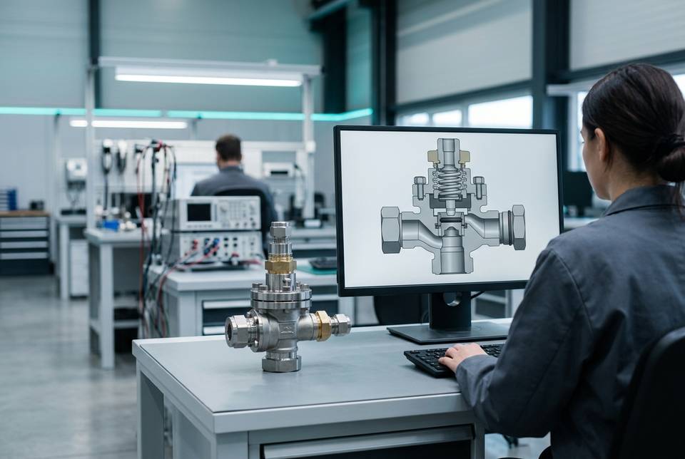
Assembled valve with a virtual CT cross-section showing seals and internal parts
Assemblies • Assembled components

Analysis of assemblies and assembled components

Taking an assembly apart changes the very clearances and compressions you want to verify, so connectors, valves, actuators and bonded units are scanned assembled. Metal inside a plastic housing creates streak artefacts that software reduces without removing them, which is taken into account when choosing how to orient the part.

FeatureDetail
ChecksPresence and position of components, clearances and interferences, seal compression, distortion, bonded and sealed joints
AdvantageThe assembly is seen as it works
LimitsArtefacts from dense metal parts next to light materials
What you receiveOriented virtual sections, clearance and position measurements, volume fly-through video
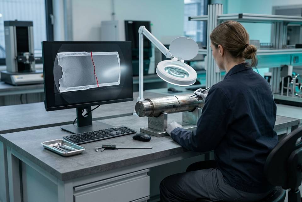
Cracked steel shaft examined in the lab, with the CT slice highlighting the fracture
Failure analysis • Before cutting

Failure analysis

On a broken part, CT comes before metallographic sectioning because it shows where to cut without destroying the evidence, for example the initiation point of a fatigue crack in a shaft fillet. The volume stays on file as a record of the part before destructive testing.

FeatureDetail
Typical casesField returns, failures in testing, leaks, supplier/customer disputes
What it showsCrack origin and path, porosity near the fracture, voids, assembly errors
DownstreamMetallography, fractography and material analysis on the indicated section planes
What you receiveReport with sections oriented on the defect, suggested cutting planes, archived volume
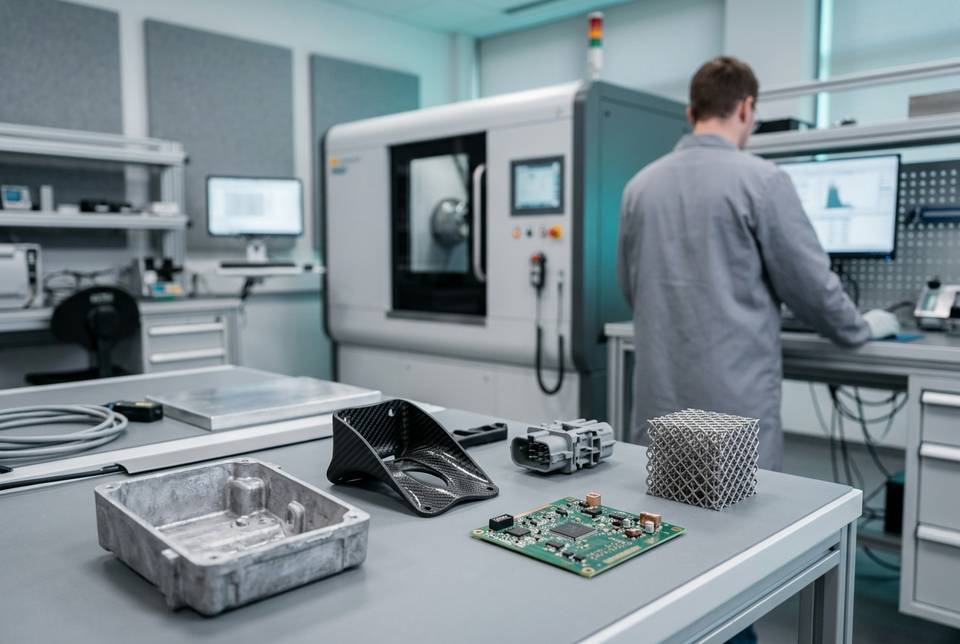
Samples of different materials for CT: aluminium casting, carbon fibre composite, plastic connector, circuit board and 3D-printed lattice
Materials • Electronics • Additive

Electronics, plastics, composites and additive manufacturing

On light materials CT reaches its finest detail, because polymers attenuate X-rays weakly. On dense metals the energy needed rises with the thickness to penetrate, and the achievable voxel size gets coarser accordingly.

What CT analyses on electronics, plastics, composites, additive manufacturing and metals
MaterialWhat is analysedTechnical note
ElectronicsSolder voids, BGA joints, wire bonds, cracks in componentsHigh contrast; very dense components create artefacts
Plastics and mouldingsSink marks, weld lines, distortion against CAD, insertsLow voltages, good contrast
CompositesFibre orientation, delamination, resin porosityGlass separates from resin better than carbon, which is closer in density
Additive manufacturingGas and lack-of-fusion porosity, trapped powder, latticesOften the only non-destructive inspection that reaches internal surfaces
Metals and light alloysCastings, die castings, forgings, weldsThick steel needs high energies

Quote for a CT analysis

With photos or a drawing, the material, the size and the question you need answered, we tell you which analysis to run and how to set it up. Quote within 24 hours.

  • Feasibility assessed on the part
  • From small components to large castings
  • NDA on request
How it works

From request to report, in five steps.

The time for each step is stated in the quote.

1. Request

Form, email or WhatsApp: describe the part and the goal, with photos, a drawing or CAD if you have them.

2. Part assessment and quote

Estimate of the resolution achievable on that part and definition of the analysis.

3. Shipping or delivery of the part

Packaging, shipping and return are agreed with the quote.

4. Scanning and reconstruction

Tube voltage, filtering, voxel size and number of projections depend on material and goal; the projections are then reconstructed into a 3D volume.

5. Report and data

PDF report and the other agreed files, with your contact available to discuss the results.

Critical zones

If the first volume shows a critical zone, a second scan targeted on that zone at a finer voxel size can be considered, without repeating the whole part.

What you receive

Report, volume, STL and CAD comparison maps.

The PDF report is always included; the other files are agreed with the quote.

Industrial CT scanning service deliverables: report, video, 3D volume, STL file, CAD comparison maps
DeliverableContentFormatWhen you need it
Technical reportResults, virtual sections, defect or dimension tables, scan conditionsPDFAlways
VideoNavigation through sections and rotation of the 3D volumeVideo fileTo show the result to production or suppliers
3D volumeReconstructed volume for further analysisBy agreementIf you have CT analysis software
STL fileMesh of external and internal surfacesSTLReverse engineering, simulation, comparison between versions
CAD comparison mapsColour-coded deviations, tolerance scale, measured dimensionsPDF and tablesMetrology, first article, verification of moulds and tooling
Reference standards for the report

Reports follow the industry standards (ASTM E1441, ASTM E1570, ISO 15708, VDI/VDE 2630), with the documentation your application requires. Current editions:

  • ASTM E1441-19(2026): standard guide for computed tomography, principles and performance parameters.
  • ASTM E1570-19(2026): fan-beam computed tomographic examination.
  • ISO 15708-1:2024 and parts 2, 3 and 4 of 2025: vocabulary, equipment, operation and interpretation, qualification.
  • VDI/VDE 2630 sheet 1.3 (2011) and sheet 2.1 (2015): CT in coordinate metrology and measurement uncertainty.

ASTM and ISO govern the examination, the VDI/VDE sheets the dimensional measurement.

Applications

Where contract CT is used most.

Foundry and die castingAutomotiveAerospaceElectronicsPlastics and mouldingIndustrial medical devicesAdditive manufacturing
Service or purchase

CT service or in-house scanner: where the numbers shift.

The service makes sense when parts are occasional or change often: prototypes, first article, a disputed batch, a failure to understand. When scans become routine on the same part family, or turnaround weighs on production, an in-house scanner starts to pay for itself.

It is often the first contract analyses that show when buying starts to make sense. The costs a machine quote does not show are discussed in industrial CT, buying a system or using a service; system families and configurations are on the industrial computed tomography and custom CT systems pages. For inline series inspection see when industrial radioscopy pays off.

FAQ

Frequently asked questions about the industrial CT scanning service

What is a CT analysis?

A CT analysis is a non-destructive inspection in which the part is X-rayed from hundreds of angles and reconstructed into a 3D volume. The volume yields porosity and cracks with their position, internal and external dimensions compared against CAD, or an STL mesh for reverse engineering. PITECH provides industrial CT inspection services for companies in Italy and Europe, with a quote within 24 hours.

Can you run a CT test on a single part?

Yes. The service also covers single parts: prototypes, first articles, a disputed or failed component. Feasibility is assessed on the part before the quote, and turnaround depends on the application.

What do you need to quote a CT scanning service?

Material, size and weight of the part, how many parts and what you need to know: defects to look for, dimensions to verify, geometry to export. Photos, a drawing or a CAD model help judge feasibility. With this information the quote arrives within 24 hours.

What is the smallest defect CT can detect?

It depends on the voxel size, which depends on the part. When the part fills the detector, the voxel is roughly the imaged diameter divided by the number of pixels: 100 mm on a 2,000-pixel detector gives about 50 µm, and at 3–5 voxels per side a pore is measurable from about 0.15–0.25 mm. A part twice as wide doubles the voxel size too.

How long does a CT analysis take?

Turnaround depends on the application: part size and material, required resolution, number of parts and type of analysis. You will find it stated in the quote.

Does the part need cutting or preparation before scanning?

No, CT needs no cutting or preparation. Assemblies should be sent assembled; for metrology the part should arrive clean, with no residue or protective coating on the surfaces to be measured.

Does CT tell you whether the part conforms?

The report provides the data; the verdict is made against the limit on your drawing or specification, because no CT standard sets how much porosity is acceptable. For aluminium, magnesium and zinc castings, the German BDG P 203 guideline gives the form in which to write the requirement, the porosity key, and leaves the values to agreement between supplier and customer.

Can the porosity percentage be compared with another lab's result?

Only under the same conditions: voxel size, segmentation method and threshold, analysed region, minimum pore size counted. To compare two suppliers, or the same one over time, write these conditions into the order. The case of two labs measuring different porosity on the same casting shows what happens when they are missing.

After the report

From report to decision.

A report is there to decide something: accept a batch, correct the process, rewrite a specification. We support that step together with your engineers.

Reading the results

Comparison between the report and the inspection you use in production today.

Specification and criteria

Measurement conditions for porosity and dimensions written on the drawing, so reports stay comparable over time.

From service to system

When volumes grow, assessment of a CT system or a radioscopy cell on your parts.

Contact

Request a quote for the CT scanning service.

Describe the part, the material and the goal: PITECH Industrial Solution replies with the proposed analysis and the quote.

Application request

Tell us about the industrial project to evaluate.

WhatsApp