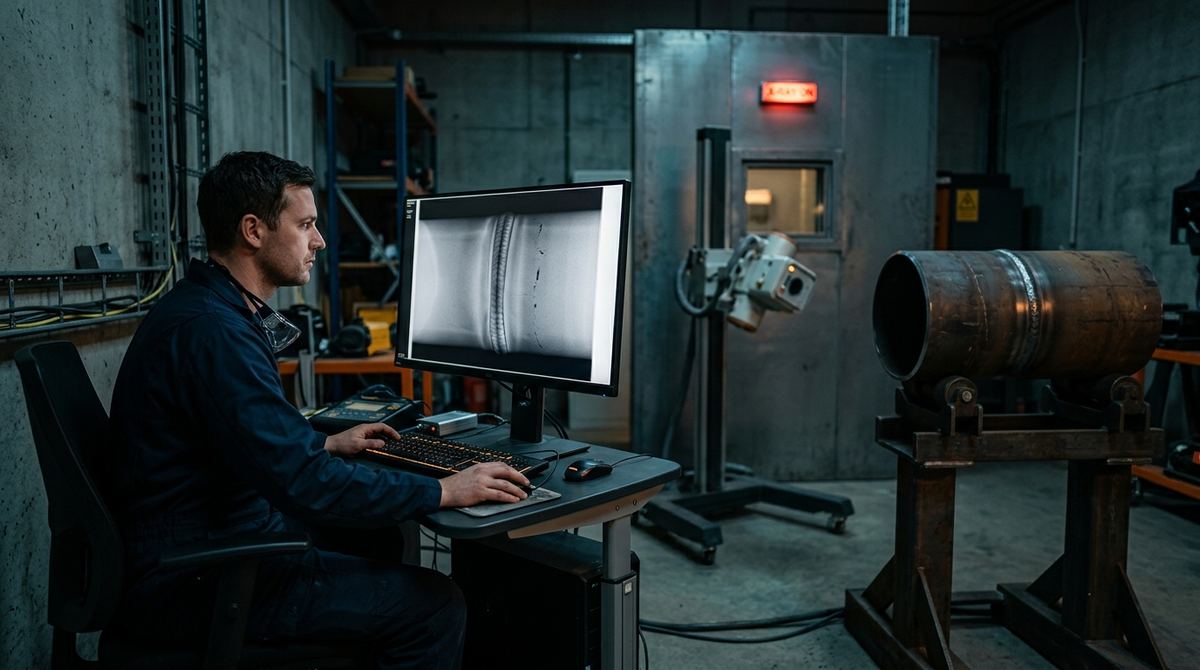
"Quality level B to ISO 5817." The line arrives inside a specification, usually copied from an earlier contract, and the engineering office reads it as a general request to do good work. That single letter has already decided which technique class the radiography has to follow, which acceptance level the indications will be judged against, and therefore how long the part sits under the beam and how many shots end up as repeats. The bill shows up on the first batch, when the images the inspection room has been producing for years stop being enough and nobody can say which standard made that happen.
Three Standards, Three Jobs That Don't Substitute for Each Other
The most common mistake in the specifications circulating today is a category error, not a detail. ISO 17636-1:2022 and ISO 17636-2:2022, the first for film techniques and the second for digital detectors, say how the image is made and how you prove it is good. The scope of Part 2 explicitly excludes acceptance levels for the indications found on digital radiographs and points to the ISO 10675 series. That series says what gets rejected: Part 1, 2021 edition, for steel, nickel, titanium and their alloys; Part 2, also 2021, for aluminium. Above both sits ISO 17635, the general standard that guides the choice of method, techniques and acceptance levels. Its current edition is the fourth, April 2025, and it replaced the 2016 edition that still appears in most specifications and most technical pages online.
So writing that a weld "is accepted to ISO 17636" attributes the criterion to a standard that doesn't contain it, rather like saying the competition rules decide who won. Two more boundaries in ISO 17635 are worth keeping in mind. It applies to completed welds, not to base material before welding or to inspection between passes, it covers steel, aluminium, nickel, titanium and their alloys, and it asks for personnel qualified to ISO 9712 or equivalent. It also does not fix the extent of testing: that comes from an application standard or from the contract specification.
| Standard | What it sets | Family |
|---|---|---|
| ISO 5817:2023 / ISO 10042:2018 | Quality levels B, C, D for the joint (steel, nickel, titanium / aluminium) | Joint quality |
| ISO 17635:2025 | Choice of method, techniques and acceptance levels; correlations | Method selection |
| ISO 17636-1:2022 / -2:2022 | How radiography is performed (film / digital detectors) and how image quality is proven | Technique |
| ISO 10675-1:2021 / -2:2021 | Acceptance levels 1, 2, 3 for radiographic indications | Acceptability |
| ISO 19232 (parts 1, 2, 4, 5) | Image quality indicators, image unsharpness and basic spatial resolution | Technique |
| ISO 16371-1:2011 | Classification of computed radiography systems | Technique |
The Letter in the Spec Picks a Row, and the Row Holds Three Cells
The tables that tie quality level, technique class and acceptance level together are not in the technique standard. They sit in ISO 10675-1 and ISO 10675-2, with one table for film radiography and one for digital detectors. The rule behind them fits in a sentence: quality level B carries technique class B and acceptance level 1, level C carries class B and level 2, level D carries class A and level 3. The table itself belongs to the standard and we don't reproduce it. The consequence does need saying plainly. Asking for the strictest acceptance level while allowing the basic technique is a combination the standard doesn't offer, and a specification written that way puts the shop somewhere no written procedure can rescue.
The person who picks the row isn't the radiographer, and that is what moves the quotation. The client picks it when setting the quality level, or the product standard picks it on the client's behalf. The scope of ISO 17635:2025 adds a warning worth carrying through intact in substance: acceptance levels are not a direct interpretation of the quality levels of ISO 5817 or ISO 10042, they relate to the overall quality of the production, and the correspondence between the two worlds holds on a general basis, not indication by indication. Annex A of that standard collects the correlations between quality levels, testing levels and acceptance levels, and it stays exactly that, a correlation annex rather than an inspection criterion.
For aluminium the pair changes name and keeps its shape: quality levels come from ISO 10042:2018 and acceptance levels from Part 2 of ISO 10675, with the same three rows. It matters most in shops that run steel fabrication and light-alloy structures side by side, with two different specifications open on the same desk.
One extra letter then moves the criterion further than it looks. Acceptance levels 3 and 2 can be specified with an X suffix, and that suffix declares any indication longer than 25 mm unacceptable, whatever the level's own calculations would permit. It is not a fourth level. It is a length constraint the client lays over the level chosen, and it shifts the reject rate without touching the quality level letter. Anyone who receives a spec with an X next to the number has received a stricter requirement than the one they are reading.
In Steel Fabrication the Designer Picks the Letter, Through the Execution Class
In steel structures the designer doesn't start from the weld quality level. The starting point is the execution class, and everything else follows. EN 1090-2:2018+A1:2024 ties fabrication, inspection and testing requirements to the EXC set in design: visual examination is always required at 100%, while the extent of supplementary non-destructive testing comes from clause 12.4.2.2 and Table 24, and the minimum waiting times after welding from Table 23. The proportion is not a fixed number. It drops for automatic or robotised processes and rises for higher steel grades, for site welds and for repairs. For EXC3 joints the acceptance criterion for imperfections is quality level B of EN ISO 5817, and the testing method is chosen among those described in ISO 17635. All of this is readable in Guidance Note 6.02 of the Steel Bridge Group published by SCI, which cites the 2024 edition of the standard; the percentages in Table 24 circulate on unauthorised copies, which is why they are not printed here.
In practice, the chain in a fabrication shop starts two links above where the engineering office expects to find it. The execution class settles the extent of testing and the quality level, the quality level settles technique class and acceptance level, and only at the end does somebody check whether the radiographic system in house can reach the class that has meanwhile been agreed by contract. Running alongside are the welding quality requirements of the ISO 3834 series, in the comprehensive, standard and elementary grades of Parts 2, 3 and 4, all in their 2021 editions: the frame in which a shop demonstrates it can produce that level, not only measure it.
What Changes in the Inspection Room When the Class Goes from A to B
The two classes carry modest names, basic techniques and improved techniques, and ISO 17636-2 treats them as regulated alternatives: class B is used where class A is not sensitive enough, techniques of even higher sensitivity are allowed if the parties agree and specify all parameters, and for digital work the choice of technique is agreed between the contracting parties in any case. Flaw visibility between film and digital counts as equivalent at equal class, and the proof runs through image quality indicators: wires to ISO 19232-1 or step and hole IQIs to ISO 19232-2 for sensitivity, the duplex wire IQI of ISO 19232-5 for unsharpness and basic spatial resolution. That last quantity entered the title of the standard with the 2018 edition, and the retitling tells the story: in digital work the deciding metric is no longer only the thinnest wire you can see.
One point speaks directly to whoever signs the specification. The informative Annex A of ISO 10675-1 notes that radiography detects volumetric imperfections readily in class A as in class B, while crack detectability depends on height, branching, opening and orientation to the beam, and that class B or better gives higher crack detectability than class A. Where the defect that worries the designer is a crack, the class stops being contractual paperwork and becomes the difference between finding and not finding.
The standard also provides the way out, and regulates it. Where a class B condition cannot be achieved for technical reasons, such as the available source or the source-to-object distance the geometry imposes, the parties may work under class A conditions while compensating the lost sensitivity with a higher minimum grey value and a higher normalised signal-to-noise ratio; the test can then be regarded as class B if the required IQI sensitivity is reached. ISO 17636-2 formalises three compensation principles, one for reduced contrast, one for insufficient detector sharpness, one for the loss introduced by bad pixel correction. This belongs in a written procedure agreed between the parties, not in a decision taken on site in front of the first part that fails.
A CR System's Class Doesn't Belong to the Imaging Plate
Computed radiography quotations keep repeating a phrase that looks like a specification and isn't: "class … imaging plate". ISO 16371-1:2011, called up as a dated reference by ISO 17636-2:2022, states in its scope that CR system classes do not refer to the imaging plates of a particular manufacturer, and that the class results from using a given imaging plate together with the exposure conditions, in particular the total exposure, the scanner type and the scanning parameters. The class is a property of the whole chain, and changing scanner or read-out parameters is enough to move it. A datasheet quoting the plate alone proves nothing about the system that will enter the inspection room.
The same standard already separates two kinds of test that commercial discussions tend to blur: manufacturer tests, which need special tooling a user laboratory normally doesn't have, and user tests, simpler ones meant for quick verification and long-term stability. A buyer should know which of the two produced the number in front of them.
Who Qualified the System, and Who Verifies It Every Year
The division of duties is sharper still in the American standards many specifications call up alongside the ISO set. ASTM E2446-24 is manufacturing characterisation: it needs specialised phantoms, states it is not intended for users, and carries the criteria by which CR systems are classified into performance levels so that systems from different suppliers become comparable. ASTM E2445/E2445M-20 for computed radiography and ASTM E2737-23 for digital detector arrays are user practices instead, meant to establish a baseline and monitor it over time, and both state plainly that they are not an acceptance test of the system. The examination itself runs to ASTM E2033/E2033M-24 for CR and ASTM E2698-18e1 for DDAs, while image exchange and archiving have their format in ASTM E2339-21, DICONDE, harmonised with medical DICOM.
For a buyer all of this reduces to one question for the supplier: which standard produced the number in the offer, and who ran it. A "certified system" without that detail isn't a comparable specification, and values from the two families, manufacturer qualification and user verification, don't compare with each other.
The Saving Digital Brings, and the Line That Eats It
On the move from film to digital, the most solid public numbers remain those collected by Uwe Ewert and Uwe Zscherpel of BAM Berlin with Klaus Bavendiek, in a paper circulated on NDT.net: companies reported exposure time reductions between 5% and 25% compared with film exposures, a processing and interpretation cycle cut to roughly a quarter of the film cycle in mobile testing and to under 5% in serial inspection of castings and welds, on top of savings on consumables and chemical waste disposal. In the same text the authors write the other half, and it is the half quotations leave out: digital does not automatically deliver film image quality, contrast sensitivity depends on exposure conditions with a real risk of misapplication, and reaching maximum sensitivity with multi-gain correction calls for exposure times that can exceed film. Those figures are manufacturer statements gathered by the authors rather than independent measurements, and the paper is well over a decade old, so they read as orders of magnitude, not as a promise.
The second-order effect is the one nobody budgets. Film never asked for periodic verification of the imaging system; digital does, and that verification has an owner, a phantom, an interval and an archive of results to maintain. It is small in money and heavy in discipline: when it lapses, what fails is not today's image but the ability to demonstrate, two years from now, that the system was in order the day that joint went through.
Who Can Sign the Report When the Image Is a File
ISO 9712:2021 covers the radiographic method among the certifiable methods and allows its system to apply to techniques within an established method, provided a complete scheme exists. The modules, though, are not written by the standard. They are written by the schemes of the certification bodies. In the BINDT PCN scheme, in a 2024 requirements document, radiographic techniques are listed separately, film, computed radiography with imaging plates, digital radiography with direct detectors, computed tomography and the interpretation-only variants, with those for direct detectors and tomography stated as still in development; for the interpretation of digital images the document asks for at least 12-bit images in DICONDE or TIFF format.
Out of this comes a misunderstanding worth defusing before signature: the abbreviation RT-D in ISO 17635:2025, with its variants for CR and DDA, designates the method, not a personnel qualification. Anyone committing to deliver reports on digital images should check with their own certification body which techniques are actually certifiable today, before promising them to a customer.
The Questions That Make Two Quotations Comparable
One practical rule falls out of the whole chain, and it holds for buying equipment as much as for negotiating a specification: whoever knows their row buys a system, whoever doesn't buys a detector and discovers the row afterwards. The information that makes two offers comparable, and that any serious evaluation asks for before a single test shot, is always the same:
- the quality level required and the document that imposes it (specification, product standard, execution class);
- material, thickness and joint geometry, aluminium included;
- the technique class that follows, and the acceptance level, with any X suffix;
- the defect of concern, volumetric or crack, because the class changes detectability;
- the source available and the distances the part imposes, which decide whether class B is achievable or has to be compensated;
- who classified the offered system and to which standard, and which periodic verification stays with you;
- data format and archiving, for traceability years later;
- the certification techniques your certification body actually offers.
PITECH works with fabricators, equipment manufacturers and laboratories to turn that line of specification into a configuration that genuinely holds it, within its digital industrial radiography solutions. The evaluation starts from the specification and the real part rather than from a catalogue: quality level required, material and thickness, defect of concern, source and space available, and from there the choice between computed radiography and digital detector arrays, with the comparison between the two covered in the guide on CR and DR in industrial radiography and the detailed criteria in the guide on choosing a DR detector for weld inspection. Where the joint is too complex for projection to settle it, the next step is industrial computed tomography. To start, describe the specification and the component from the contact page.
Frequently asked questions on weld radiography acceptance levels
Does ISO 17636 contain weld acceptance criteria?
No, and it says so in its own scope: ISO 17636-2:2022 specifies how radiography with digital detectors is performed and how image quality is demonstrated, but it does not specify acceptance levels for the indications found, referring instead to the ISO 10675 series. Acceptance levels live in ISO 10675-1:2021 for steel, nickel, titanium and their alloys, and in ISO 10675-2:2021 for aluminium. A specification that accepts a weld "according to ISO 17636" gives a technique standard the job of an acceptability standard.
What does the X suffix mean in ISO 10675 acceptance levels?
It means no indication longer than 25 mm is acceptable, whatever the level's own calculations would allow. The suffix can be specified on acceptance levels 3 and 2 of ISO 10675-1 and ISO 10675-2, and it is not a fourth level: it is an extra length constraint the client adds on top of the level chosen. Level 1, already stricter, does not carry it.
Can radiography be performed in class A when the specification asks for quality level B?
Not as a free choice. The tables in ISO 10675-1 and ISO 10675-2 tie the weld quality level to both the technique class and the acceptance level: quality level B goes with technique class B and acceptance level 1, quality level C with class B and level 2, quality level D with class A and level 3. ISO 17636-2 does provide a regulated way out: where a class B condition cannot be achieved for technical reasons, the parties may work under class A conditions while compensating with a higher minimum grey value and a higher normalised signal-to-noise ratio, provided the required image quality indicator sensitivity is reached.
Does the class of a computed radiography system depend on the imaging plate?
No. ISO 16371-1:2011, called up as a dated reference by ISO 17636-2:2022, states that CR system classes do not refer to the imaging plates of a particular manufacturer: the class results from using a given imaging plate together with the exposure conditions, the scanner type and the scanning parameters. A datasheet quoting the class of the plate alone proves nothing about the system that will actually run in the inspection room.
Which standard sets how many welds must be radiographed?
Not ISO 17635, which refers the extent of testing to an application standard or to the contract specification. In steel structures, the extent of supplementary non-destructive testing is set by EN 1090-2:2018+A1:2024 according to the execution class, with 100% visual examination always required and a proportion that drops for automated processes and rises for higher steel grades, site welds and repairs. In pressure equipment and other sectors the extent comes from the design code or from the client's specification.
Who can interpret and sign a digital radiograph?
Personnel certified to ISO 9712:2021 or an equivalent scheme, for the specific technique the certification body's scheme provides. The standard covers the radiographic method and allows certification for techniques within an established method, but the modules are defined by the schemes: in the BINDT PCN scheme, for example, film, computed radiography, direct-detector digital radiography, computed tomography and the interpretation-only variants are listed as separate techniques. The abbreviation RT-D used in ISO 17635:2025 designates the digital radiographic method, not a personnel qualification.