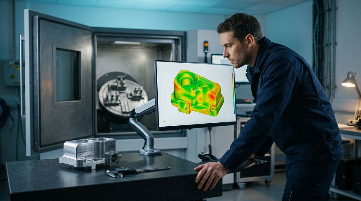
A hydraulic manifold can pass every external check and still leak on the test bench, because an internal bore, the one no gauge reaches, is two hundredths of a millimeter out of tolerance. While the part stays whole, that dimension can't be measured. You estimate it, or you cut the part open to read it in section and scrap it in the process. A tactile CMM and an optical scanner stop at the same place, for the same reason, because they measure where the stylus or the light can reach, and inside a closed cavity neither one reaches. On the metrology side, industrial computed tomography exists to close that gap. It reconstructs the part as a volume and measures what sits inside, without opening it.
The stylus touches, CT passes through
The difference between CT and conventional measuring instruments comes down to how each one reaches the surface. A tactile coordinate measuring machine (CMM) touches the part with a stylus and records the coordinates of the points it can physically reach. An optical scanner projects structured light or laser and captures the surface it can see. Both work well as long as the geometry to be measured is exposed. CT instead acquires hundreds of radiographs as the part rotates, and from those projections it reconstructs a volume made of voxels, the three-dimensional pixel of the scan. In that volume every surface, external and internal, becomes a measurable point, because the X-ray beam has passed through the full thickness. It's the same technology as CT for defect analysis in castings, aimed at a different goal, measuring a dimension rather than finding a pore. The two uses even sit in separate standards worlds. For the fundamentals of the technique, from reconstruction to artifacts, see the industrial CT scanning guide.
From voxel to CAD comparison
The reconstructed volume yields the same quantities you would measure on the bench: bore diameters, center distances, wall thicknesses, flatness, GD&T features. The difference is that they come out together, inside and out, from a single acquisition. The operation that changes first-article work the most, though, is the comparison against the nominal model. The CT volume is aligned to the part's CAD, and the deviation of every point of the real surface from the theoretical one is plotted. The result is a false-color map showing where the part carries excess material and where it falls short. On a die casting, on an additive component or on a plastic molding, that map shows at a glance where shrinkage, distortion or mold wear are moving the geometry. A set of point measurements would raise the suspicion much later. On moldings CT also measures warpage against the tool, within the limits of filled polymers and parts with metal inserts described in the article on CT scanning of plastic and composite parts.
This is why CT metrology took hold where the critical dimensions sit inside the part. In aerospace they're the cooling channels of a blade or the thin walls of an additive bracket, geometry no stylus travels. In automotive they're die-cast housings and e-mobility components, where hole spacing and wall thickness decide the fit. In medical they're internal lumens and the porosity of implants, to be measured without cutting a part destined for the human body. In all three, the first article is when internal measurement is worth the most, because that's where you decide whether the mold, the build program or the process is on target, before the series starts.
How far you can trust it: uncertainty is task-specific
The first question any quality department asks is how far the number can be trusted, and the honest answer is not a single figure. CT accuracy depends on the part, the material, the geometry and the scan parameters, and it has to be stated for that specific task. The survey by Kruth and colleagues in CIRP Annals (2011), the founding text of the field, frames the whole subject around traceability to the meter and measurement uncertainty, not around image resolution. The German guideline VDI/VDE 2630, Part 2.1 (2015 edition), sets out how task-specific uncertainty is determined, along with the suitability of the measuring process against the tolerance to be held. Part 1.2 lists the variables that influence the result.
The practical route to a number is the substitution method, borrowed from ISO 15530-3 for tactile CMMs and adapted to CT. You measure a calibrated reference part, geometrically similar to the object, and anchor the CT measurement to that traceable value. Because both measurements happen under the same conditions, the method captures machine errors, environmental effects, evaluation strategy and operator in one pass. It has a cost, because it takes a series of repeated measurements on the calibrated part, and against CT scan times that is no detail. Müller, Hiller, De Chiffre and co-authors (CIRP Journal of Manufacturing Science and Technology, 2014) applied exactly this procedure to CT, with repeated measurements on a calibrated master piece. Stating the voxel size, by contrast, doesn't prove the uncertainty achieved, and that's the point most specifications confuse.
Among the influencing variables listed in Part 1.2, one weighs more than the others and is often invisible in the report: surface determination, the gray-value threshold the software uses to decide where the material ends. Moving it slightly moves the edges, and with them diameters and wall thicknesses, systematically. The same mechanism that makes two labs disagree on porosity, told in CT porosity: same casting, two different numbers, acts on dimensions too. It matters even more when a model is derived from the volume, as in reverse engineering with industrial CT. A serious metrology report therefore states the surface determination method next to the dimension.
Is there an internal dimension you can't measure today?
Send us the drawing or CAD, the material and the critical dimension with its tolerance: we will tell you whether CT can measure it with adequate uncertainty and arrange a demonstration scan on one of your parts, with no obligation. Tailored quote within 24 hours.
Email us Message us on WhatsAppCT, tactile CMM or optical scanner: what each measures
The three technologies don't compete on the same ground, and choosing well means knowing where each one gives way. On an accessible external feature at a tight tolerance, the tactile CMM stays the reference, because it touches a few points at the lowest uncertainty there is. The optical scanner is unbeatable for speed on free-form external surfaces, where a dense cloud is needed in seconds, but on closed geometry and on shiny or deep surfaces it's as blind as the CMM. CT covers the whole volume, internal included, in a single scan, and it doesn't deform compliant parts because it never touches them.
The head-to-head on internal geometry is documented. A study in Precision Engineering (Villarraga-Gómez, Lee and Smith, 2018) measured the same artifacts with CT and with a tactile CMM. On internal features the deviation between the two was below 5 µm in most cases, with CT expanded uncertainties between 1 and 20 µm. On compliant parts, where the stylus applies a force that deforms, CT and a zero-force CMM converged to within ±2 µm.
| Technique | Where it's strongest | Blind spot |
|---|---|---|
| Tactile CMM | Accessible external features, lowest uncertainty | Closed internal geometry; compliant parts deformed by probing; slow point-by-point |
| Optical scanner | Free-form external surfaces, dense and fast cloud | Inside the part; shiny, transparent or deep surfaces |
| Computed tomography | Full volume, internal and external, no contact | Task-specific uncertainty; large or highly absorbing parts; cost and time |
The criterion then writes itself. If the dimension that decides the part is external, accessible and must be certified at the lowest uncertainty, the tactile CMM is the choice. For a free-form external surface to capture fast, the optical scanner is the tool. If instead the dimension sits inside the part, if the component is too complex or too compliant to be touched, or if internal and external have to be measured in the same run, CT is the only one of the three that answers.
When CT isn't the answer
Here the limits weigh as much as the advantages. CT costs and takes time, and on large or highly absorbing parts, a thick steel block, beam absorption drives uncertainty up until the measurement becomes less reliable than a good tactile pass. There's a standards picture to know as well. The standard dedicated to CT as a coordinate measuring system, ISO 10360-11, is still at draft stage. System acceptance today therefore leans on VDI/VDE 2630 (Part 1.3, which applies ISO 10360 to CT sensors) and on ASME B89.4.23-2020. A buyer can call up the latter in the order to verify the stated accuracy specifications, both at acceptance and at periodic reverification. There's no third way here that specifications keep looking for. Either you qualify task uncertainty with a calibrated part similar to the object, accepting the substitution method's time, or the value CT returns stays an indication, not a certifiable dimension.
Start with the dimension you can't measure today
The most useful entry point is almost always one specific dimension, the one you currently estimate or read by sacrificing a part to sectioning. Pick a component on which that dimension is already known by other means, for example a part sectioned or measured by touch before assembly, scan it and compare the CT value with the reference. That is the substitution method in its simplest form, and one test tells you whether CT holds the tolerance. Through the contract CT metrology service the measurement can also be ordered for single parts or a first article inspection, with a deviation map, a table of dimensions and stated measurement conditions. When the measurements become routine, the comparison between an outside service and an in-house system has its own numbers, set out in the article on industrial CT: buying a system or using a service.
What to send us for an assessment
To tell you whether CT can measure your dimension with adequate uncertainty, we need a few precise details:
- drawing or CAD model, with the critical dimensions and their tolerances;
- material, overall size and maximum thickness to penetrate;
- which dimensions are internal or out of reach for stylus and optics;
- how you measure or estimate them today (sectioning, gauges, CMM);
- number of parts, and whether this is first article, mold validation or a recurring check;
- any calibrated or previously measured part, useful as a reference.
You can send them by email to info@pitech-solution.com or on WhatsApp, with drawings or CAD attached.
A CT dimension belongs on a certificate only if an uncertainty determined for the task, and the method that produced it, sit next to the value. If the dimension that worries you is inside the part, the next step is to measure it once against a known reference. For castings, where the same scan also counts pores, see the article on porosity in castings and die castings.
Frequently asked questions on CT metrology and dimensional measurement
Does CT replace the coordinate measuring machine?
No, the two techniques complement each other. On an accessible external feature at a tight tolerance the tactile CMM stays the reference, because it touches a few points at the lowest available uncertainty. CT becomes indispensable where the CMM is blind: closed internal geometry, channels, undercuts and parts too compliant to touch without deforming them. On compliant parts, the study by Villarraga-Gómez, Lee and Smith (Precision Engineering, 2018) found CT and a zero-force CMM in agreement within ±2 µm.
How accurate is a CT dimensional measurement?
There is no single figure that holds universally, because accuracy depends on part, material, geometry and scan parameters and has to be stated for the specific task, as VDI/VDE 2630 Part 2.1 requires. The practical way to quantify it is the substitution method of ISO 15530-3:2011, adapted to CT, in which you measure a calibrated part similar to the object and anchor the measurement to that traceable value. In the Precision Engineering study (2018), CT expanded uncertainties on internal features ranged from 1 to 20 µm.
How does CAD-to-part comparison work in CT?
The reconstructed CT volume is aligned to the nominal CAD model, and the deviation of every point of the real surface from the theoretical one is shown as a false-color map. Excess material appears on one side, missing material on the other. The result depends on the alignment chosen, so the report has to say which datums were used. With a different alignment the same map can change color without the part changing at all.
Is there a standard for using CT as a measuring instrument?
The main reference is the VDI/VDE 2630 guideline series (Part 1.1 fundamentals, 1.2 influencing variables, 1.3 application of ISO 10360 to CT sensors, 2.1 task-specific uncertainty). ISO 10360-11, dedicated to CT as a coordinate measuring system, is still a draft. For performance evaluation, ASME B89.4.23-2020 can be called up in the purchase order. ISO 15708, by contrast, treats CT as a non-destructive testing method.
What should a CT metrology report contain?
Besides the deviation map and the table of dimensions, the conditions that let someone repeat the measurement: voxel size, surface determination method, alignment datums and part temperature. For temperature, ISO 1:2022 sets 20 °C as the reference for geometrical specifications. For dimensions that go on a certificate, it also needs the uncertainty for that dimension and the method used to determine it.