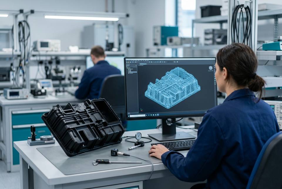
A spare part with no drawing is the most common reverse engineering job in a maintenance shop. The pump is thirty years old, its maker is gone, and the part is worn but still in one piece. An optical scanner captures the outside in minutes; a coordinate measuring machine gets the dimensions its probe can reach. Internal channels, closed cavities and the bottom of an undercut blind hole stay out of reach of both. CT captures them together with the outside in a single acquisition. That's why it becomes the reverse engineering tool whenever the inside of a part matters.
Between the part on the bench and a model a design office can use, though, there are three different objects that everyone calls "the model", and each step has its own rules. Knowing them helps you ask for the right thing and judge how far to trust what comes back.
Volume, Mesh, CAD: Three Files Everyone Calls "the Model"
The first is the reconstructed volume. CT acquires hundreds or thousands of X-ray projections while the part rotates and reconstructs them into a three-dimensional grid of voxels. Each voxel holds a grey value proportional to the material's attenuation at that point. The volume is the most complete record, but no design software opens it.
The second is the mesh, usually an STL file: a surface made of triangles that approximates the boundaries between material and air, outside and inside. It's the format that inspection software, simulation tools and 3D printers read. It's also a poor format. An STL file holds only the triangulated surface: no material, colour or internal structure, and no information on which face is a plane or a cylinder. Those very limits are why ISO/ASTM 52915:2020 defined the richer AMF format for additive manufacturing. A mesh describes shape, not design intent.
The third is the parametric CAD model, made of mathematical surfaces and features (planes, cylinders, fillets, holes with their axes) and exportable as STEP under ISO 10303-242:2025. It's the only one of the three where a designer can change a dimension. Várady, Martin and Cox, in the introductory paper published in Computer-Aided Design in 1997 and still cited as a reference, describe reverse engineering as exactly this chain: data capture, segmentation of the point cloud or mesh into regions, fitting of simple and free-form surfaces, merging of multiple views and building a consistent CAD model. CT works on the first link. The rest is modelling work.
The Surface Isn't in the Volume: a Threshold Decides It
A CT volume contains grey values, not edges. Getting to a mesh means deciding where material ends and air begins, and that decision, called surface determination, fixes much of the model's accuracy. The simplest method takes the grey value halfway between the air peak and the material peak (the so-called ISO-50% threshold) and applies it to the whole volume. Local methods search, point by point, for the maximum grey-level gradient near the edge. They hold up better when intensity varies across the part.
Shifting the threshold has a precise effect. If the surface moves outwards, external dimensions grow and hole diameters shrink, and vice versa. On a model meant to produce a spare part, that error adds up systematically on every fit. A whole guideline, VDI/VDE 2630 Blatt 1.2:2018-06, is devoted to the variables that influence a CT measurement. Borges de Oliveira and co-authors (Case Studies in Nondestructive Testing and Evaluation, 2016) compared ISO-50% thresholding, local thresholding and region growing on calibrated step gauges in PEEK, PPS and aluminium, scanned alone and in combination. Their practical conclusion is uncomfortable: scan settings and surface determination parameters are hard to choose, and users often fall back on the software defaults. On multi-material parts, where a single threshold can't suit both boundaries, the choice weighs even more.
Then there's scale. Voxel size comes from machine geometry, the distances between source, part and detector, and a small error in those distances becomes a proportional error on every measurement. PTB, Germany's national metrology institute, describes a procedure that keeps both under control. The threshold for internal and external geometry is derived from the CT deviations measured on a calibrated hollow cylinder, scale is corrected with a ball bar, and uncertainty is determined with calibrated workpieces under ISO/TS 15530-3. That way, the institute reports, task-specific uncertainties smaller than the voxel edge were achieved. For reverse engineering, the minimum version of the same rule is to measure one or two dimensions separately, with a calliper or a CMM, and check the mesh scale before using it.
How Accurate a CT Mesh Really Is
An honest answer starts with a comparison. Between 2009 and 2011 the University of Padova coordinated the first international intercomparison of CT for dimensional metrology, the "CT Audit": fifteen systems in Europe, America and Asia, run by expert users, measured the same reference objects. Reporting the results in CIRP Annals in 2012, Carmignato highlighted how hard users find it to evaluate the uncertainty of their own CT measurements, given the many error sources and the lack of standards. The number to look at, then, is the stated uncertainty for the dimension that matters, not the system's resolution.
For verifying a CT system used as a measuring machine, the reference in force in Europe is VDI/VDE 2630 Blatt 1.3:2011, which applies the ISO 10360 logic for coordinate measuring machines to systems with a CT sensor. In the United States there's ASME B89.4.23-2020. The ISO 10360 part dedicated to CT, Part 11, is still in preparation: the ISO/DIS draft dates from 2021 and no published edition exists. The uncertainty of a specific dimension, on that material and geometry, is determined with VDI/VDE 2630 Blatt 2.1:2015-06 by repeatedly measuring a calibrated part similar to the one being captured. These tools were written for dimensional measurement, but they apply to reverse engineering too. A model only makes sense if you know the uncertainty with which it reproduces the dimensions you'll use.
In practice the accuracy of a CT mesh depends on three things, in this order. Voxel size, set by the part itself: a component 100 mm across on a 2,000-pixel detector scans at about 50 µm, and the mesh can't describe details smaller than a few voxels. Material and thickness, because thick steel needs high energies that cut contrast and worsen beam hardening. And surface determination, covered above. On compact plastic or light-alloy parts the mesh is generally more faithful than on a large steel casting, where CT may not get through at all.
Do you have a part to rebuild without a drawing?
Send us photos, the material and size of the part, and tell us what the model is for: we'll tell you which voxel size is achievable and what you'll receive. Quote in 24 hours.
Email us Message us on WhatsAppOptical Scanner, CMM or CT: Who Sees What
The three techniques don't compete on the same ground. Each has a domain where it's the cheapest choice, and the table lays them side by side.
| Criterion | Optical scanner (structured light, laser) | Tactile CMM | Industrial CT |
|---|---|---|---|
| Internal geometry and closed cavities | No | Only what the probe can reach | Yes, in the same scan as the outside |
| Shiny, black or transparent surfaces | Often need matting spray | No effect | No effect |
| Large or very dense parts | Suitable, even beyond a metre | Limited by machine travel | Limited by penetration and field of view |
| Data returned | Point cloud or mesh of the outer surface | Points and dimensions on probed features | Full volume, external and internal mesh |
| Verification references | ISO 10360-13:2021 | ISO 10360-2:2009 | VDI/VDE 2630 Blatt 1.3:2011, ASME B89.4.23-2020 |
The verdict comes from the part's geometry. When the shape is all external, large or freeform, like a die or a body panel, an optical scanner is the fastest and cheapest choice. When a few tight-tolerance dimensions matter, a fit or a centre distance, the tactile CMM remains the reference for uncertainty. CT wins when the model must contain internal geometry, and the review by Kruth, Bartscher, Carmignato and co-authors in CIRP Annals (2011) points to a second advantage: the same scan combines dimensional and material inspection. It also pays off when surfaces are hard for optics or when an assembly needs capturing without taking it apart. Often the best answer is a combination: CT for the complete shape and two or three tactile dimensions to check its scale.
A comparison published by Gapinski and co-authors (Procedia Engineering, 2014), who measured the same part with a tactile CMM, an optical scanner and CT, gives a sense of scale. The CT results were comparable to the other two methods, with differences below 0.05 mm. The same paper spells out each method's limits. The CMM leaves gaps between probed points, the optical scanner struggled inside small-diameter holes, with errors in position and diameter, and CT is limited by penetration and artefacts. The figure holds for that part and those machines, not as a general rule.
From Mesh to CAD: the Work the Scan Doesn't Do
The mesh records the part as it is, with wear, burrs, moulding shrinkage and machining errors. The CAD model has to describe the part as it should be. A hole measured at 9.98 mm is in all likelihood a 10 H7; a face tilted by a few hundredths of a degree was meant to be perpendicular. Those calls are made by the person modelling, not by CT. That's why serious reverse engineering starts from several samples where they exist and picks the least worn as the reference.
Two pieces of information the volume doesn't provide at all. The first is tolerances, which the designer has to reassign based on function. The second is the material. CT tells a metal from a plastic, not one stainless steel from another. Knowing which alloy to order takes a composition check, which for metals takes seconds with XRF material analysis. On a plastic moulding, finally, the part is smaller than the tool because of shrinkage. If the model is meant to rebuild the tool, shrinkage has to be compensated.
When the model is meant to 3D print an identical part, or to simulate flow in internal channels, the mesh can be enough as it is, provided it's closed and free of holes. That's where CT shortens the road the most.
How to Prepare a CT Reverse Engineering Job
The first thing to state is what the model is for, because it drives voxel size and deliverables: a copy to print, a spare part to machine, a simulation, a comparison between two versions of the part. Then the part itself. It should arrive clean, without grease, thick paint or residue in the cavities, because CT captures those too. If it belongs to an assembly and the relative position of components matters, send it assembled.
For reverse engineering, the PITECH CT scanning service delivers an STL mesh of external and internal surfaces, with check sections and a report stating the scan conditions. Other mesh formats are available by agreement, and achievable fidelity is estimated during the assessment from the attainable voxel size, as described in the section on reverse engineering and STL export. If you also need a parametric CAD model, say so in the request so that feasibility is assessed together with the quote. When scans become routine, for spare parts across a machine fleet for instance, custom industrial CT systems become worth discussing.
What to Send Us for an Evaluation
To tell you which voxel size is achievable and what you'll receive, we need a few details:
- photos of the part from several sides, with overall size and weight;
- material, even approximate (steel, aluminium, plastic, composite);
- what the model is for: 3D printing, a new machined spare, simulation, comparison with another version;
- the geometry that matters most: channels, cavities, holes, fits, with critical dimensions if known;
- preferred delivery format (STL, other mesh formats) and whether a parametric CAD model is needed;
- number of samples available and their state of wear;
- any non-disclosure agreement to sign before shipping.
You can send them by email to info@pitech-solution.com or on WhatsApp, with the photos attached.
The practical rule is to look inside the part before choosing the tool. If everything the model must contain is visible from outside, an optical scanner is enough and costs less. If an important part of it sits inside, CT is the only method that delivers it without cutting the part open. In that case the next step is a scan of your best sample through our CT scanning service, with a quote in 24 hours. The overview of industrial computed tomography helps set expectations for what the volume can show.
FAQ on CT reverse engineering
What does CT reverse engineering deliver?
An STL mesh of the part's external and internal surfaces, including channels and closed cavities, extracted from the reconstructed volume, with check sections and the scan conditions. The mesh describes shape; tolerances, material and design intent are added by whoever builds the CAD model.
How accurate is an STL mesh from CT?
It depends on voxel size, which depends on part size, on the material and on surface determination. A 100 mm part on a 2,000-pixel detector scans at about 50 µm. The uncertainty of the dimensions that matter is determined under VDI/VDE 2630 Blatt 2.1, and two tactile dimensions help check the scale.
CT or an optical 3D scanner for reverse engineering?
An optical scanner is faster and cheaper when the geometry is all external, even on large parts. CT pays off when the model must contain internal geometry, when surfaces are shiny, black or transparent, or when an assembly must be captured without taking it apart. The two are often combined with a few tactile dimensions.
Does CT deliver a CAD file directly?
No. It delivers a volume and, from it, a triangulated mesh. A parametric STEP model needs modelling work that recognises planes, cylinders and holes and reassigns nominal dimensions and tolerances. If you need the CAD model too, say so in the request so that feasibility is assessed with the quote.
Can large steel parts be reverse engineered by CT?
It depends on thickness and size. Thick steel needs high energies, which cut contrast and worsen beam hardening, and beyond a certain thickness CT doesn't get through. In those cases an optical scanner for the outside and a targeted CT scan of the internal areas can be the right combination.
What do you need to quote a CT reverse engineering job?
Photos of the part, material, size and weight, what the model is for (3D printing, spare part, simulation), critical geometry, delivery format and the number of samples available. With these details PITECH prepares a quote in 24 hours; a non-disclosure agreement can be signed before shipping on request.