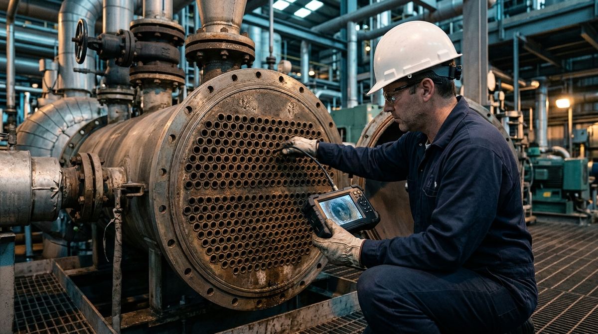
Every planned shutdown reaches the moment when someone stands in front of an exchanger with the channel head open and has to call it: the bundle comes out, or it stays. A turnaround schedule has no slack for suspicion. Pulling a bundle means cranes, flanges, new gaskets, final testing, whole days of a contested window; leaving it in place means signing off on its fitness until the next shutdown. For years that call was made from history files, heat-transfer losses and the judgment of whoever knows the plant best. The videoscope changed it at the root, because it enters the tubes with only the heads open and brings back the one piece of information that can move the verdict: what is actually in there.
Inside the Tubes, Damage Wears Different Faces
Engineers who inspect cooling-water-side exchangers learn to recognize a progression. The first alarm is usually thermal, and it arrives before any camera does: the exchanger underperforms. API RP 571 — the American Petroleum Institute's compendium of more than sixty damage mechanisms for fixed equipment, each with susceptible materials, critical factors and recommended inspection methods — points to fouling as the first suspect. Inside the tube, though, a deposit that cuts heat transfer is rarely just a performance problem. Local chemistry changes underneath it, and under-deposit corrosion works under cover: the surface the water jet cleaned may look sound while the metal beneath the remaining deposits keeps losing thickness.
The most treacherous case is microbiologically influenced corrosion, MIC. Bacterial colonies build tubercles that pass for ordinary scale. Underneath, in carbon steels, the classic morphology is a pit within a pit; in stainless grades, sub-surface cavities grow with an opening small out of all proportion to the missing metal. An operator who simply counts visible pits underestimates the damage almost by construction. Reading the images therefore takes the same competence as acquiring them: the videoscope documents morphology, and knowledge of the mechanisms turns that morphology into a diagnosis. One prerequisite no datasheet can work around: a dirty tube shows the deposit, not the metal. The inspection is planned after hydroblasting, and the quality of the cleaning sets the quality of the diagnosis.
The Exchanger Picks the Probe
Before any comparison between models, probe selection is an exercise in geometry. Tube bundles built to TEMA practice use eight standard outside diameters, and two dominate the installed base: 19.05 mm (3/4 in) and 25.4 mm (1 in). Subtract the wall thickness and the usable bore typically lands between 15 and 21 mm. Through that bore must pass the probe, its illumination and enough clearance to keep the optics off the deposits. That is why 4 mm and 6 mm probes have become the de facto standard for bundle work, with 8 mm versions where the bore allows and more light is needed.
Working length weighs as much as diameter, and gets underestimated more often. Tubes in removable-bundle exchangers typically run 3,600 to 9,000 mm, and fixed-tubesheet designs reach 15,000: a probe inspecting from the tube end has to cover the full length, which pushes useful configurations to 7.5 metres and beyond, against the 1.5–7.5 m of standard probes and special builds of 10–15 m. Inside a straight tube, tip articulation matters less than it does in a turbine, but optical centering and measurement remain decisive: stereo and shadow techniques size a pit directly from the image and set it against an acceptance criterion, instead of filing away a photograph and an opinion. How these requirements translate into purchasing specifications is covered in detail in the videoscope selection guide.
From the Tubesheet to the Final Report
An inspection that produces a decision, rather than a collection of videos, is built before the instrument is switched on. Access comes first: which heads will be open, in what sequence relative to cleaning, how much of the turnaround window each item of equipment gets. Coverage on the tubesheet comes next. Inspecting every one of several hundred tubes isn't always compatible with the schedule, so selection follows the logic of the damage: inlet zones where erosion works, peripheral tubes and stagnation zones where deposits build, plus tubes already plugged in previous shutdowns, which carry the history of the equipment. Every inspected tube gets identified on the tubesheet map with its finding, because the value of the report lives in the comparison with the next shutdown.
On procedure and documentation, the reference is ASME BPVC Section V, Article 9, which governs direct and remote visual examination: personnel requirements, minimum lighting, written procedure, recording of results. Acceptance criteria beyond the Code requirements are a matter of agreement between the contracting parties, and they are best fixed before the inspection, not in front of the images. For timing, API 570 sets the cadence on piping: Class 1 requires thickness measurements and external visual inspection at least every 5 years or, if less, every half of the calculated remaining life; Class 2 stretches to 10 years. That "if less" is the intelligent half of the rule, because it shortens intervals precisely where corrosion runs. Skipping the planning stage doesn't save time; it relocates it, turning the inspection into a set of unreferenced images that nobody, six months later, can place on a specific tube.
On process piping, the method changes little; the access changes a lot. Entry comes through an opened flange, a removed valve, a nozzle, and the choice of points follows the damage mechanisms once again: API RP 571 concentrates localized corrosion at injection points, in dead legs where the fluid stagnates, and downstream of changes in direction, which is exactly where the optics should go. The videoscope earns its keep where external thickness readings are blind or impractical: weld root verification on new lines before commissioning, the search for deposits and blockages, visual confirmation of an indication the thickness gauges flagged at a condition monitoring location. The time-comparison logic applies here too: one image tied to a precise point on the line, repeated at every shutdown, is worth more than a hundred unreferenced ones.
What the Camera Will Never Measure
A serious supplier says it before you find out: the videoscope sees the surface, and the surface isn't the thickness. Stereo measurement sizes a pit that breaks the surface, but it can't say how much wall remains underneath, can't see thinning from the shell side, can't quantify distributed metal loss. Those numbers belong to other methods: ultrasonic thickness measurement, the IRIS technique for full wall mapping of a tube, eddy current methods for fast screening of non-ferromagnetic materials. The mature workflow lines them up: the videoscope as the diagnostic screening that ranks the tubes and identifies the damage mechanisms, the quantitative techniques concentrated on the tubes the screening flagged. Asking the camera for a thickness value is a framing error. Using it to decide where to measure is its actual job.
The Turnaround Ledger Is Kept in Days, Not Images
The economics of videoscope inspection need no invented figures, because the reasoning stands on its own. Opening heads is a matter of hours; pulling a bundle is a matter of days, and the days of a planned shutdown are the most contested resource a plant owns. Every bundle pulled "to be safe" and found healthy is a window of crane time and specialist labour spent confirming a doubt. Every bundle left in service unseen is a bet that comes due at the next shutdown. Videoscope screening trims both tails: bundles get ranked by real condition, extractions and retubing concentrate where the damage is, and materials get ordered early, while tube lead times still fit the calendar. The return on the operation grows with the quality of the diagnosis, which is why instrument, cleaning and reading competence should be treated as one package. The same approach, carried over to gas turbines and engines, is described in the guide to borescope inspection of turbines.
See It Work on Your Own Plant
The honest trial of a videoscope doesn't happen in a meeting room. It happens on a real exchanger, with its tubes, its deposits and its history. PITECH, within its industrial videoscopy RVI solutions, distributes industrial videoscopes with interchangeable probes in the diameters and lengths tube bundles demand, and structures the evaluation as a field demonstration: a representative item of equipment is chosen, probe coverage is verified against actual tube diameters and lengths, images and measurements are taken on real defects, and the report format the inspector and the end customer will have to accept is built together. A tube bundle gets opened for what has been seen, not for what is feared. To arrange a demonstration on your own plant, describe the equipment and its geometries on the contact page.
Frequently asked questions on videoscope inspection of heat exchangers and piping
What can a videoscope actually show inside heat exchanger tubes?
After proper cleaning of the bundle, a videoscope shows the real condition of the internal surface: residual deposits and fouling, pitting, under-deposit corrosion, the tubercles typical of microbiologically influenced corrosion (MIC), erosion at inlet zones, visible cracks and mechanical damage. These are the damage mechanisms API RP 571 catalogues for cooling-water-side exchangers. Diagnosis quality depends on the preliminary cleaning: a dirty tube shows the deposit, not the metal, so the inspection is planned after hydroblasting.
Which probe do you need to inspect a tube bundle?
The bundle geometry dictates the probe. TEMA standardizes eight tube outside diameters, and by far the most common are 19.05 mm (3/4 in) and 25.4 mm (1 in): once wall thickness is subtracted, the usable inside diameter typically falls below 15–21 mm, which makes 4 mm and 6 mm probes the practical compromise between access, illumination and image quality. Working length matters as much as diameter: with tubes running 3,600 to 9,000 mm, the probe must cover the full tube from the insertion end, so configurations of 7.5 metres or more are needed (standard probes run 1.5–7.5 m, with versions up to 10–15 m).
Does a videoscope measure remaining tube wall thickness?
No. A videoscope sees the internal surface and, with stereo or shadow measurement, sizes what breaks that surface: the diameter and local depth of a pit, the extent of a damaged area. It does not quantify remaining wall thickness or metal loss from the shell side of the tube: that requires ultrasonic testing, the IRIS technique or eddy current methods. The sound workflow uses the videoscope as a diagnostic screening tool to decide where to measure and with which technique, not as a substitute for measurement.
Which codes and standards apply to remote visual inspection?
Direct and remote visual examination is governed by ASME BPVC Section V, Article 9, which sets requirements for personnel, lighting, written procedure and documentation; acceptance criteria beyond the Code requirements are a matter of agreement between the contracting parties. For in-service piping, API 570 sets the intervals: for Class 1 piping, thickness measurements and external visual inspection at least every 5 years or, if less, every half of the calculated remaining life; for Class 2, up to 10 years. The lesser-of-the-two rule shortens intervals exactly where corrosion runs fastest.
When does videoscope inspection beat a full opening?
Opening the channel heads of an exchanger is a matter of hours; pulling the bundle is a matter of days, between cranes, flanges, gaskets and final testing. Videoscope inspection works in that gap: with only the heads open, it shows the internal condition of the tubes, ranks bundles by actual condition, and concentrates extractions, UT/IRIS measurements and retubing only where they are needed, with materials ordered in advance rather than mid-turnaround. It does not replace opening when damage is there; it avoids opening when it is not, and that is where the turnaround days are recovered.