What non-destructive testing means
A girth weld on a pressure pipeline can look flawless and still hide, halfway through the wall, a ten-millimeter lack of fusion. Finding it without cutting the pipe is the job of non-destructive testing, the family of methods that examine materials, components and joints without impairing their later use. The inspected part remains a saleable part, which is the real difference from destructive tests such as tensile, bend or macro-etch tests, performed on specimens that are sacrificed.
In English the usual acronym is NDT, and technical documents also use NDE (non-destructive evaluation) and NDI (non-destructive inspection). In Italy the same field is called CND, controlli non distruttivi, or PND for prove non distruttive. The language of the specification changes, while the methods, the ISO standards and the personnel qualification stay exactly the same.
What NDT is used for becomes clear at three moments in the life of a component. During production it decides whether a casting, a weld or a forging meets the required quality level, and it lets the plant correct the process before scrap piles up. At incoming inspection it confirms that alloy and thickness match what the supplier certified. In service it measures corrosion, fatigue cracks and wear on equipment that cannot stand idle for long, and gives the maintenance manager the data needed to repair, replace or extend the life of an asset.
Each method exploits a specific physical phenomenon, whether reflected light, the capillary action of a liquid, magnetic flux leakage, electromagnetic induction, the propagation of elastic waves, the attenuation of ionizing radiation or X-ray fluorescence. Physics decides what a method can see and what it misses, so no single technique covers every defect.
What are the non-destructive testing methods: the main techniques
In ISO 9712:2021, the standard for personnel certification, the methods carry codes now used worldwide: VT for visual testing, PT for penetrant testing, MT for magnetic particle testing, ET for eddy current testing, UT for ultrasonic testing and RT for radiographic testing. Acoustic emission, thermography and leak testing complete the list, yet eight families cover the vast majority of industrial cases. PITECH supplies equipment and services for remote visual inspection, ultrasonics, radiography, computed tomography and XRF analysis, while penetrant, magnetic particle and eddy current testing are described here for completeness, without a dedicated offering.
Direct and remote visual testing (VT, RVI)
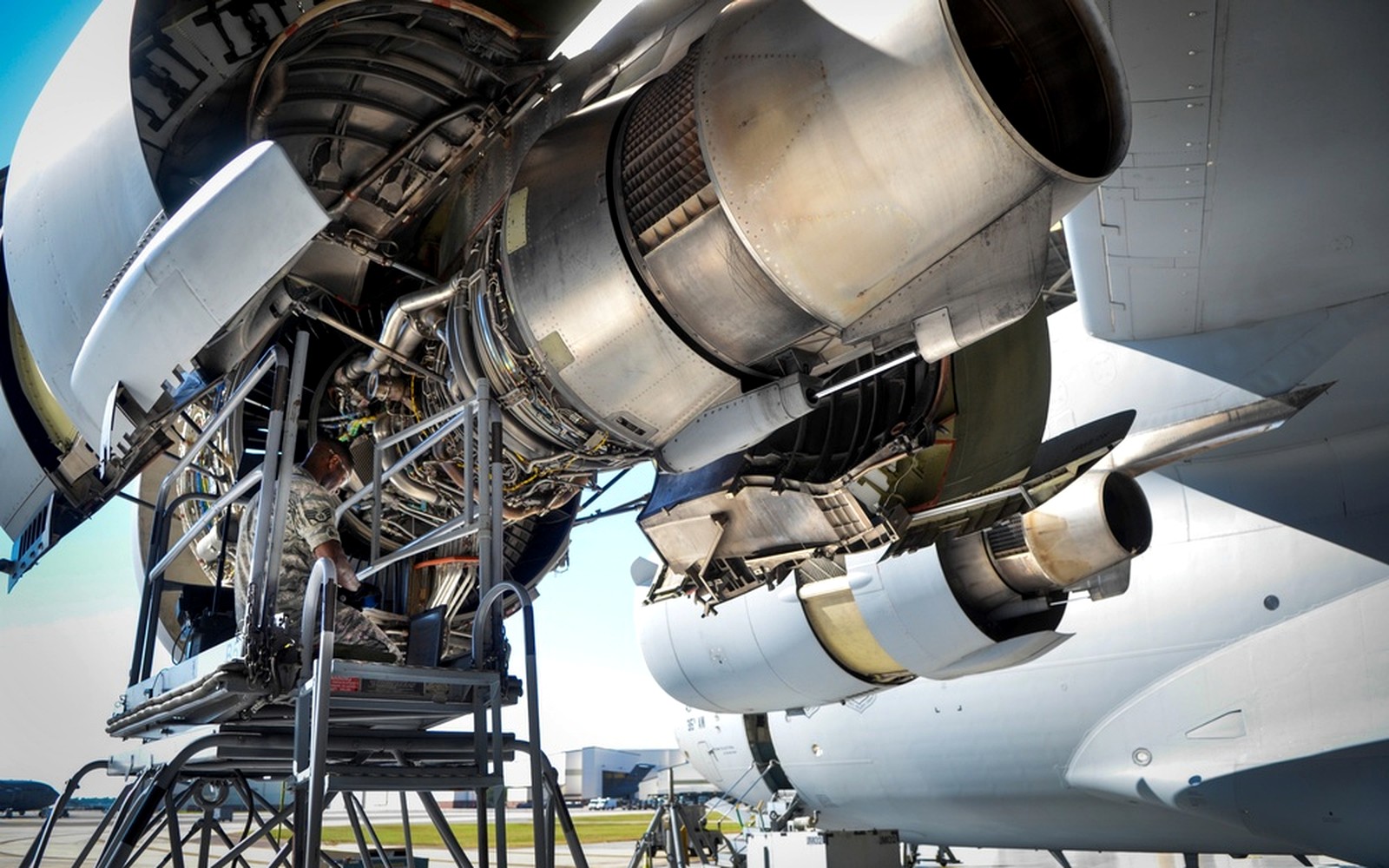
It is the first test and the least expensive. The inspector examines the surface with the naked eye or with lenses, mirrors and suitable lighting, following the principles of EN 13018:2016. When the area cannot be reached, as inside a turbine, a heat exchanger or a hollow casting, remote visual inspection takes over with borescopes, endoscopes and articulating videoscopes. The method finds visible surface cracks, corrosion, erosion and foreign objects, and on welds the shape imperfections such as undercut, excess weld metal and misalignment.
Its limit matches its strength, since it only sees what reaches the surface, with a sensitivity tied to lighting, distance, viewing angle and probe resolution. For cavities and closed components the reference is the page on industrial videoscopes and borescopes for remote inspection, and probe selection is covered in the article on how to choose an industrial videoscope.
Penetrant testing (PT)
A colored or fluorescent liquid, applied to a clean surface, is drawn by capillary action into open discontinuities. Once the excess is removed, a developer pulls it back to the surface and outlines the indication. ISO 3452-1:2021 sets out the general principles. The method works on ferrous and non-ferrous metals, ceramics and non-porous plastics, and reveals cracks, surface porosity, laps and lack of fusion open to the surface.
Below the surface it sees nothing, and a discontinuity sealed by paint, oxide or peening goes undetected. Surface preparation affects the result more than the choice of product.
Magnetic particle testing (MT)
The part is magnetized and sprayed with ferromagnetic particles, dry or in suspension. Where a crack interrupts the flux, the leakage field gathers the particles and makes the flaw visible. The principles are described in ISO 9934-1:2016. On ferromagnetic materials MT is faster and more sensitive than penetrant testing for surface cracks, and it also picks up those lying just below the surface.
Sensitivity drops quickly with depth and depends on the orientation of the flaw relative to the field, which is why parts are magnetized in two directions. Austenitic stainless steels, aluminum, copper and titanium cannot be magnetized and are excluded.
Ultrasonic testing (UT, PAUT, TOFD)
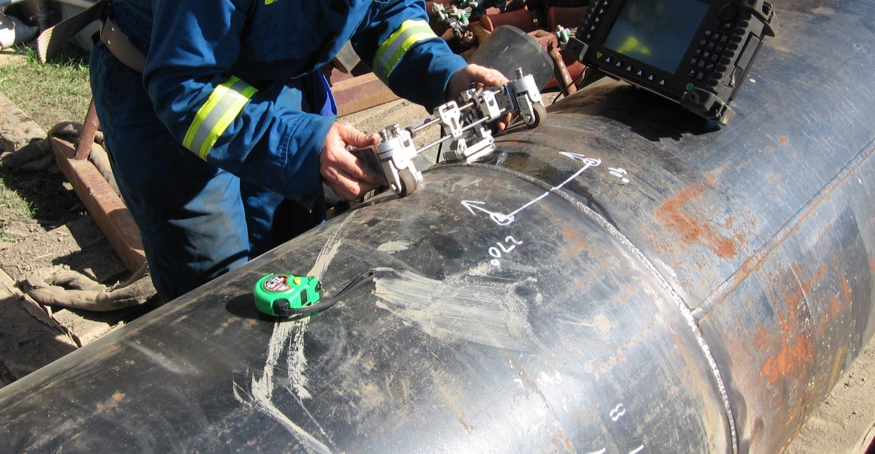
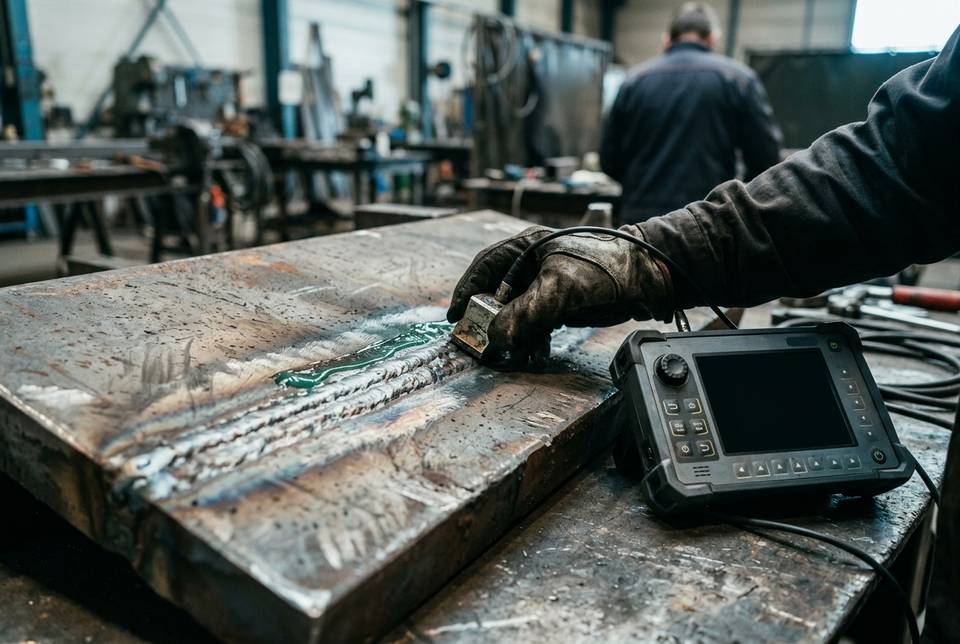
A probe sends elastic waves in the megahertz range into the material and records the echoes reflected by discontinuities or by the back wall. Time of flight gives depth and thickness, while echo amplitude and shape describe the reflector. The general principles are in ISO 16810:2024. Phased array (PAUT) uses multi-element probes that steer and focus the beam electronically and produce recordable images, while TOFD relies on diffraction at the tips of a flaw to measure its height with good accuracy.
Ultrasonics perform best on planar defects such as cracks and lack of fusion, on laminations and on thickness and corrosion measurement, even with access from one side only. They do need a couplant, they struggle with coarse-grained materials such as austenitic welds and many castings, and on walls only a few millimeters thick the dead zone near the surface becomes a problem. Instruments and probes are presented on the page on industrial ultrasonic testing with UT, PAUT and TOFD. To judge when phased array is worth it, read the article on how PAUT works and when it pays off, and for corrosion the one on the ultrasonic thickness gauge.
Industrial radiography (RT): film, CR, DR and radioscopy
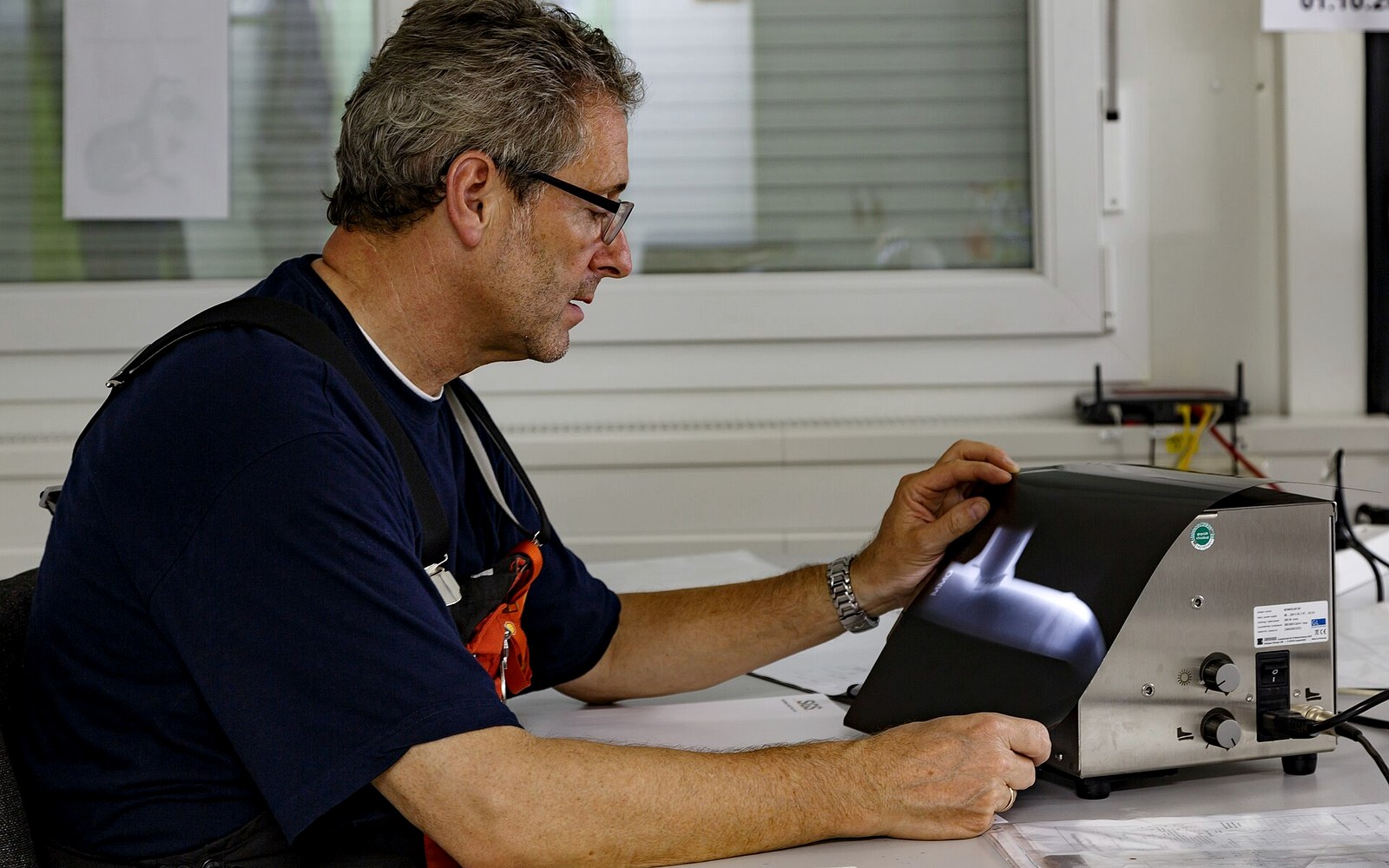
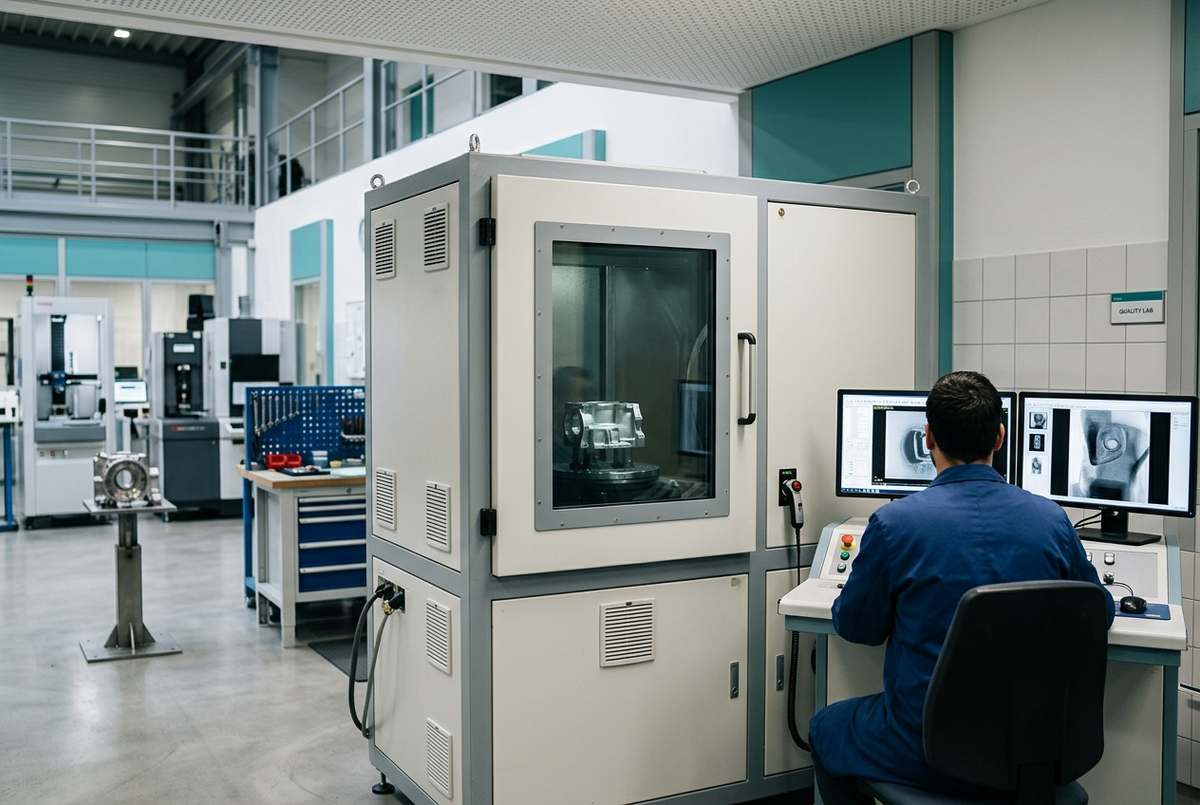
An X-ray or gamma beam passes through the part and is attenuated differently where the material is thicker, denser or missing. The detector records that difference as a projected image. It used to be film, and today it is more and more often the phosphor imaging plates of computed radiography (CR) or the digital panels of direct radiography (DR), which deliver the image within seconds. With a fast detector and a moving part the technique becomes radioscopy, used for in-line inspection of castings. For welds, the techniques are set by ISO 17636-1:2022 for film and ISO 17636-2:2022 for digital detectors.
Radiography documents volumetric defects very well, namely porosity, slag inclusions, shrinkage and cavities in castings, and it leaves an image that can be archived and reviewed by third parties. A single projection does not reveal the depth of a flaw, though, thin cracks show up only when aligned with the beam, and the method needs access to both sides of the part and a controlled area for radiation protection. The two digital routes are compared in the article on computed and direct radiography side by side, while sources, detectors and accessories are on the page on industrial radiography.
Computed tomography (CT)
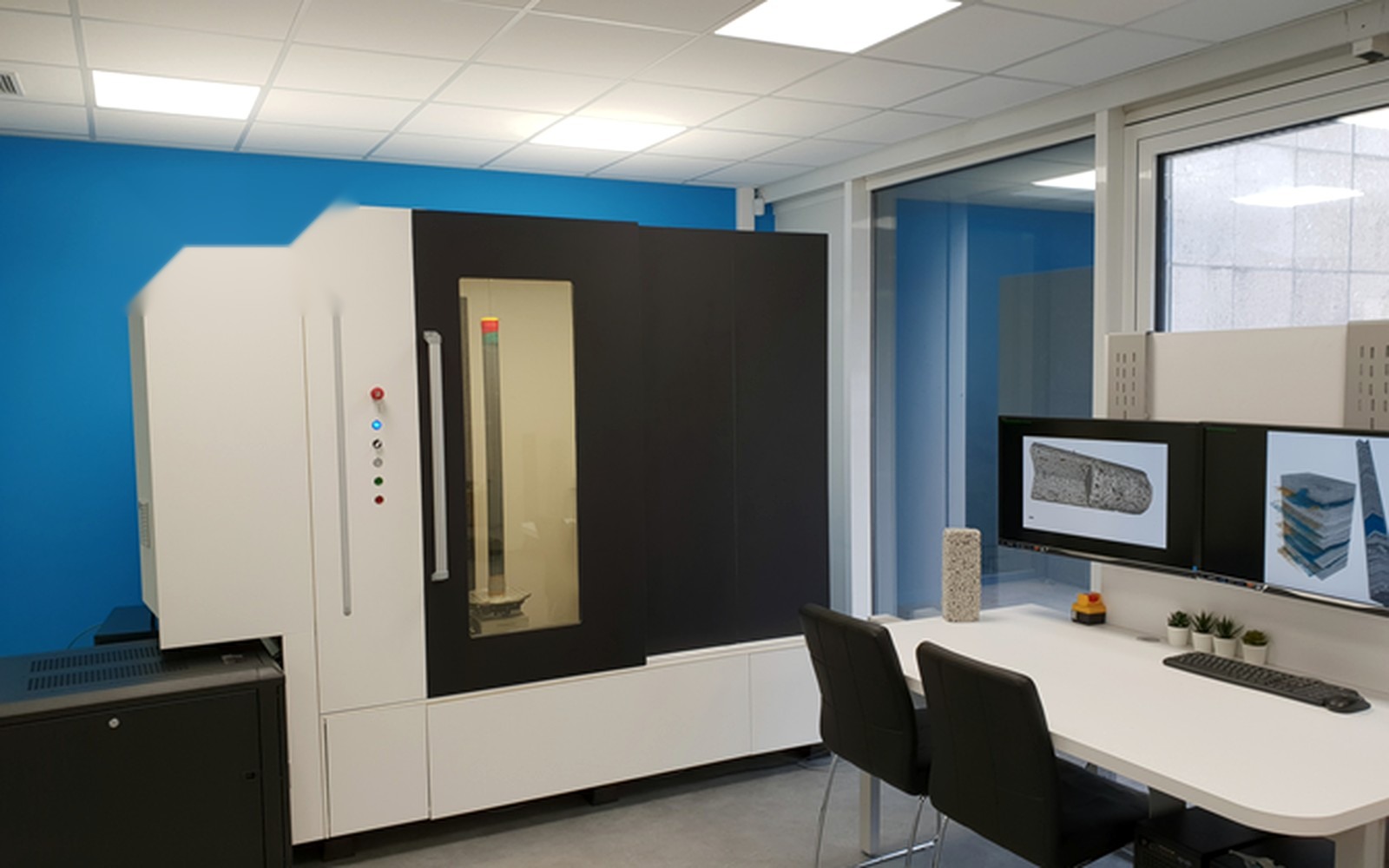
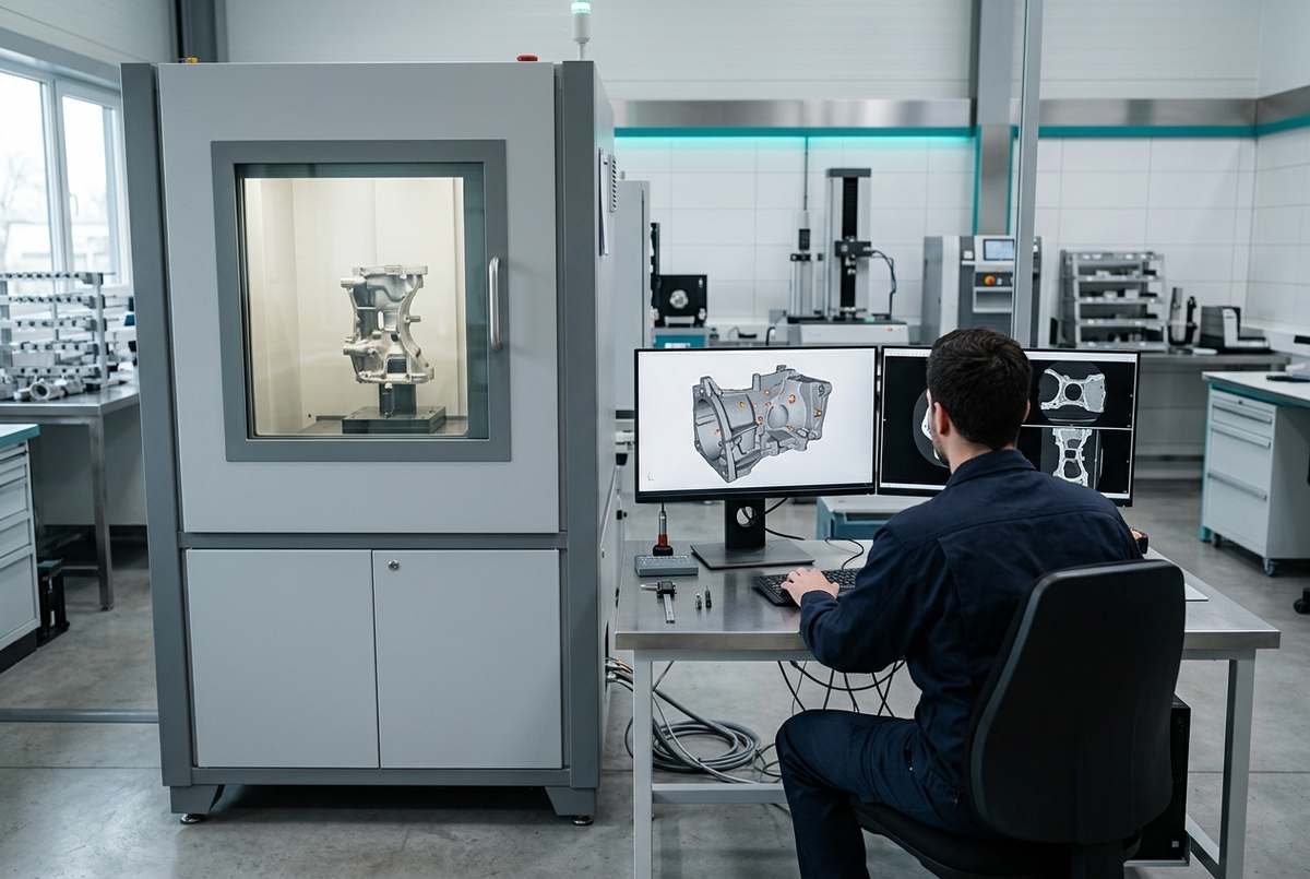
Tomography acquires hundreds or thousands of radiographs of the part as it rotates in front of the beam and reconstructs its volume in three dimensions. Every pore, inclusion or cavity gets a measurable position and volume, and internal dimensions that a contact coordinate measuring machine cannot reach become verifiable. Principles, equipment and samples are described in ISO 15708-2:2025.
The price of so much information is time, from minutes to hours per scan, together with a resolution that worsens as parts get larger, because the voxel grows with the field of view. That is why CT serves prototypes, first-article inspection, failure analysis and critical batches rather than one hundred percent of production. The page on industrial computed tomography explains what can be measured, and the article on porosity in castings measured by CT covers the most frequent case.
Eddy current testing (ET)
A coil carrying alternating current induces eddy currents in a conductive material. A crack or a change in thickness disturbs their path and alters the coil impedance, which the instrument displays on the complex plane. The principles are in ISO 15549:2019, and the application to welds, mainly ferritic ones, is in ISO 17643:2015. The method is fast, needs neither contact nor consumables, and lends itself to automation on tubes, bars and bolt holes.
Because of the skin effect the currents concentrate near the surface, so the depth examined is limited. The signal also reacts to permeability, lift-off and geometry, and the method works only on conductive materials.
Material analysis with XRF and PMI
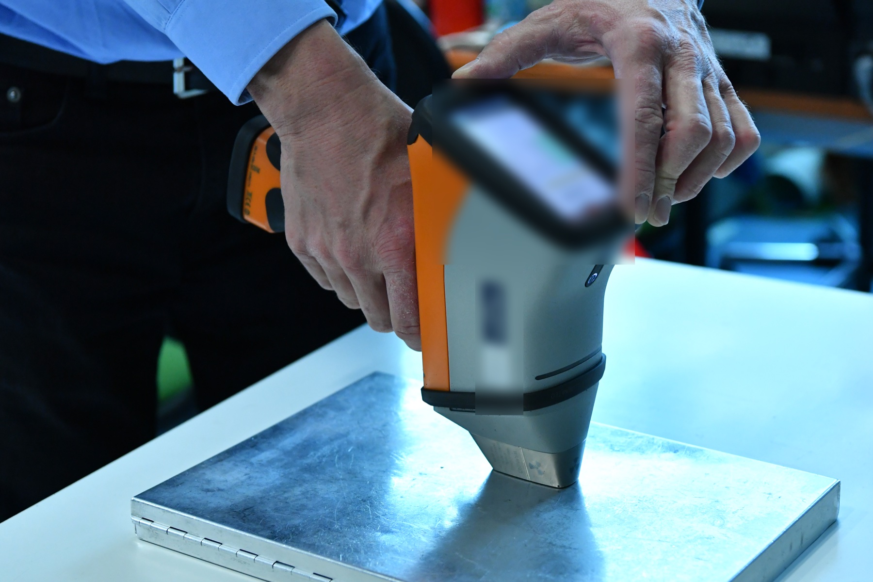
X-ray fluorescence does not look for defects. It answers another quality question, namely whether the material is the right one. The instrument's X-ray tube excites the atoms of the sample, which emit X-rays at energies characteristic of each element, and the intensity of those lines yields the composition. In positive material identification (PMI) a handheld analyzer identifies the alloy of pipes, flanges, valves and welds within seconds, without taking samples.
Handheld XRF does not measure carbon and struggles with light elements. Separating low-carbon steel grades therefore calls for LIBS or spark optical emission spectrometry, as explained in the article on LIBS and XRF for carbon measurement. The instruments are presented on the page dedicated to XRF and PMI material analysis.
Which method for which defect and material
The choice always starts from the defect you are worried about and from the material. The table sums up the combinations met most often in industry, and special cases must be checked against the product standard.
| Requirement | Suitable methods | Materials | Limits to consider |
|---|---|---|---|
| Surface-breaking defects: cracks, surface porosity | VT, PT, MT, ET | PT on almost all non-porous materials, MT ferromagnetic only, ET conductive | Clean, accessible surface; paint and oxide mask indications |
| Near-surface defects | MT, ET | Ferromagnetic (MT), conductive (ET) | A few millimeters at most, sensitivity falls with depth |
| Internal volumetric defects: porosity, inclusions, shrinkage | RT, CT, UT | Steels, light alloys, composites, plastics | Thickness and density set energy and time; CT is limited by part size |
| Internal planar defects: cracks, lack of fusion | UT, PAUT, TOFD; RT if the flaw is aligned with the beam | Steels and fine-grained metals | Coarse grain and austenitic welds need dedicated procedures |
| Wall thickness, corrosion and erosion | UT (thickness gauging and mapping), tangential RT, RVI for appearance | Piping, tanks, pressure vessels in service | Coupling, coatings, wall temperature |
| Internal geometry and 3D measurement | CT | Castings, additive manufacturing parts, assemblies, plastics | Scan time and part size |
| Composition and alloy identification | XRF, LIBS, spark OES | Metals and alloys | Handheld XRF does not measure carbon |
In practice methods are combined. A surface test and a volumetric test on the same joint cover different defects, and tomography steps in when radiography has shown an indication that needs to be located or measured. The most frequent comparison, X-rays against ultrasound on welds, is discussed in the article on radiography or ultrasonic testing for weld inspection.
Non-destructive testing of welds: the tests normally performed

On structural steelwork, pressure vessels and piping the typical sequence is almost always the same. It starts with visual testing, usually on every joint and in line with ISO 17637:2016, because many shape imperfections are visible and a joint rejected by eye does not deserve more expensive tests. Then comes a surface method, penetrant testing on any material or magnetic particle testing on ferritic steels, and a volumetric method, radiography or ultrasonics, on the percentage of joints required by the product standard or the contract.
The standard that ties these choices together is ISO 17635:2025, with the general rules for testing welds in metallic materials. It guides method selection according to quality requirements, material, thickness, welding process and extent of testing. In the 2016 edition, for butt welds in ferritic steel, radiography was the reference up to 8 mm, the two volumetric methods were on equal terms between 8 and 40 mm and ultrasonics prevailed above that. The 2025 edition revised that table, so it must be read in the current text. For austenitic steels and dissimilar joints, ultrasonics require dedicated procedures and radiography often remains the starting point.
The quality required of the joint is expressed by levels B, C and D of ISO 5817:2023 for steel, nickel, titanium and their alloys, where B is the most stringent; aluminum falls under ISO 10042. The criteria used to judge indications sit in the acceptance standards of each method instead. Radiography uses ISO 10675-1:2021, ultrasonic testing of full-penetration joints from 8 to 100 mm uses ISO 11666:2018, and penetrant and magnetic particle testing use ISO 23277:2015 and ISO 23278:2015. ISO 17635 itself warns that acceptance levels are not an automatic translation of quality levels, and the reason is physical, because each method sees an imperfection differently.
Who decides what goes into the specification, and how to read the correspondence between quality level and acceptance level, is explained in the article on acceptance levels in weld radiography. Typical defects in joints and castings, with the images that go with them, are collected in the case studies on welds and castings, and anyone weighing phased array will find the criteria for choosing a PAUT and TOFD instrument.
Do you have welds or components to inspect?
Send us material, thickness, joint or part type and the governing standard: we will recommend the right method and equipment, with a tailored quote within 24 hours.
Email us Message us on WhatsAppWho performs the tests: personnel qualification under ISO 9712
A non-destructive test is only as good as the operator who performs it and the procedure behind it. ISO 9712:2021 defines how operators are qualified and certified, method by method and sector by sector, through an independent certification body. Candidates need a general exam on the physics of the method, a sector-specific exam and a practical test on specimens with known flaws, plus a minimum period of industrial experience and near-vision acuity checked every year.
There are three levels. Level 1 personnel carry out tests according to written instructions and under supervision. Those holding Level 2 set up the equipment, perform and supervise tests, interpret and evaluate results against the applicable standards, and write instructions and reports. Level 3 develops and validates techniques and procedures, interprets standards and specifications and is responsible for the whole process. A certificate is valid for five years, after which it is renewed, and recertification is required at ten years.
Aerospace commonly relies on employer-based qualification under EN 4179, with similar requirements but a different logic. In every case buying an instrument does not qualify the person using it, and the budget of an in-house NDT project must include training, exams and the Level 3 time needed to write procedures.
In-house equipment or external service
The answer depends mostly on how often the test recurs. With daily or weekly inspections, tight turnaround times and qualified staff on hand, in-house equipment pays for itself and frees production from laboratory queues. With occasional needs, very expensive methods or missing skills, an external service remains the rational choice. Tomography is the typical example: many companies start with an industrial CT scanning service and consider buying only when volumes justify it, following the reasoning in the article on buying a CT system or using an external service. For X-rays the same calculation appears in the article on buying an industrial X-ray system, and companies with special cabinet or automation needs will find the options among the custom industrial CT systems.
What to send us for an assessment
To recommend the right method, equipment or service we need a few concrete details about your case.
- type of component or joint, with drawing or photo and dimensions;
- material or alloy and thicknesses to be inspected;
- defects you are concerned about and minimum size to detect;
- product standard, quality level or customer specification;
- stage of the test: production, incoming inspection or in-service maintenance;
- annual volumes or test frequency;
- method used today and qualified staff available.
You can send them by email to info@pitech-solution.com or on WhatsApp, attaching drawings and photos.
The rule worth keeping is simple. Defect and material come first, then the standard that governs acceptance, and technology comes last. If your case involves radiography, tomography, ultrasonics, remote visual inspection or alloy analysis, the next step is an assessment on your own parts, with a tailored quote within 24 hours. For a deeper look at one method at a time, see the technical resources on non-destructive testing.